Page 9
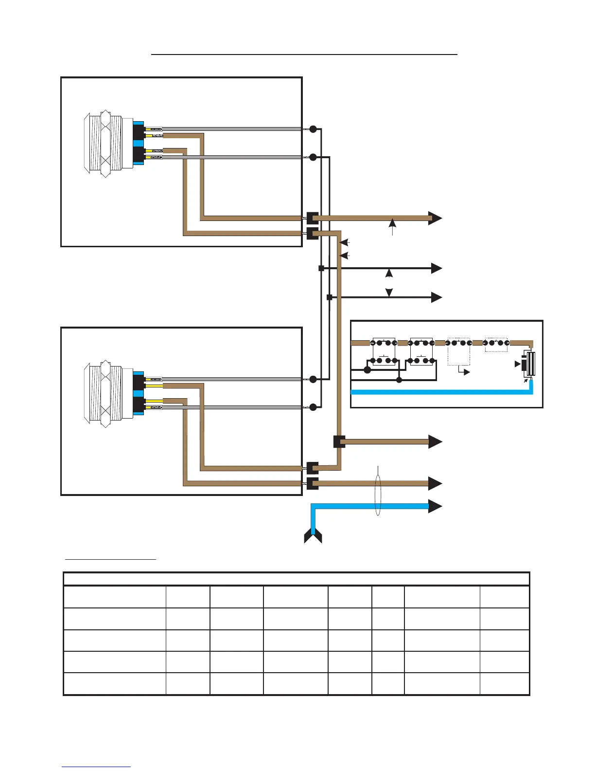
Handset Auxiliary Equipment Connections.
1
4
Set J1 up
and J2 down
DR
VT
0V
BZ
S2
S1
DS
X
EX
V-
V+
CB
ED+ Series Handsets
Entroview Series handsets
and Apartment Stations
WE/BE
BE/WE
WE/OE
TRG
RESET
COM
COM
N/C
N/C
N/O
N/O
12V
0V
Mountcastle Relay
2 sets of volt free C/O contacts
rated at 1 amp.
Note :-
The EX connection is
only used on these
accessories and additional
handsets. Do not
fit a wire into EX for
any other purpose.
Note: Fit jumper link PL4
to enable EX output
Marshalling
Marshalling
Note: These volt free contacts
maybe used to trigger door bells,
additional sounders, Silent Bell
units etc using external power
supplies. An example of using
a door bell is shown below.
RELAY
TRG
RESET
COM
COM
N/C
N/C
N/O
N/O
12V
0V
Door
Bell
PSU
230~
Input
Door
Bell
+
_
Front Door Bell Push
(if fitted).
Delay off time adjust
Flashing Beacon
Black
Red
Timer ENT9876/1
TRG
0v 12v
COM
N/C
N/O
RELAY
TRG
RESET
COM
COM
N/C
N/C
N/O
N/O
12V
0V
EliteMAN0113/ 10 of 12
EliteMAN0113/ 9 of 12
124 3 3
Microswitch
Grey Wire = 16/0.2 (NO Connection).
Brown Wire = 1.5mm (NC Connection).
FS4 or 5 Fire Switch
124 3
Microswitch
Grey Wire = 16/0.2 (NO Connection).
Brown Wire = 1.5mm (NC Connection).
PTE/EPTE Push to Exit Switch
To Push to Exit Common
See wire ‘C’ in table.
To Push to Exit Input
See wire ‘B’ in table.
To Lock 12v Supply
See wire ‘A’ in table.
2
1.5mm Flex (Brown)
To Lock +
To Lock -
From System Switched Negative
See table below
2
1.5mm 2 core Flex
Brown Wire
Blue Wire
CW1308 2 Pair
A
Link Wire (A2)
C
D
E
Connection Terminal: Apex DP Elite Cont. Entrocare DP E100 E2000 KMS Simple Key PAC 512
B
2
Wire A (Brown 1.5mm )
Wire B (CW1308)
Wire C (CW1308)
2
Wire D (Brown 1.5mm )
2
Wire E (Blue 1.5mm )
PL1/12V
PL6/12V
(PL28/12V)
PL1/12V
12V Lock
2/+12V
PL3/0V PL3/0V
PL3/PE PL3/PE
Lock +
or BGU
Lock +
or BGU
Lock +
or BGU
Lock +
or BGU
Lock +
or BGU
Lock +
or BGU
Lock +
or BGU
PL1/NC PL1/NC
PL5/C
(PL33/C)
PL5/PE
(PL33/PE)
PL6/NC
(PL28/NC)
Door1 0V
(Door2 0v)
Door1REX
(Door2REX)
Door1 NC
Relay
(Door2 NC)
31/N/C
(34/N/C)
11/GND
DC Out +
Door Lock1 NC
(Door Lock 2 NC)
GND 1
(GND 2)
RTE 1
(RTE 2)
9/OL1
(10/OL2)
Access/Lock
Door 1 0V
(Door 2 0V)
Door 1 RTE
(Door 2 RTE)
Lock 1 NC
(Lock 2 NC)
Connection Table:
Note: Connections in brackets are for 2nd door connections. Also note if system Door Entry DE then all connections
for locks are made at the Door Entry System (i.e. Access Controllers trigger Door Entry PE inputs with a NO 0V).
From ‘A’ if PTE Only
Page 10
FS4/5 & PTE/EPTE Wiring Diagram.
NC
NO
NC
NO
FS
PTE
A
A2
D D
+
-
D
C
B
1N4007
Diode
E
If Fitted
Fail Safe Lock
FA/
AOV
BGU
Schematic
I/O BY
Others
FA/AOV
NC
NC
Grey Wire = 16/0.2 (NO Connection).
Brown Wire = 1.5mm (NC Connection).
Grey Wire = 16/0.2 (NO Connection).
Brown Wire = 1.5mm (NC Connection).
0v
12v
TRG
NO
12v
0v
TRG
TRG
12v
0v
COM
NO
TRG
 Loading...