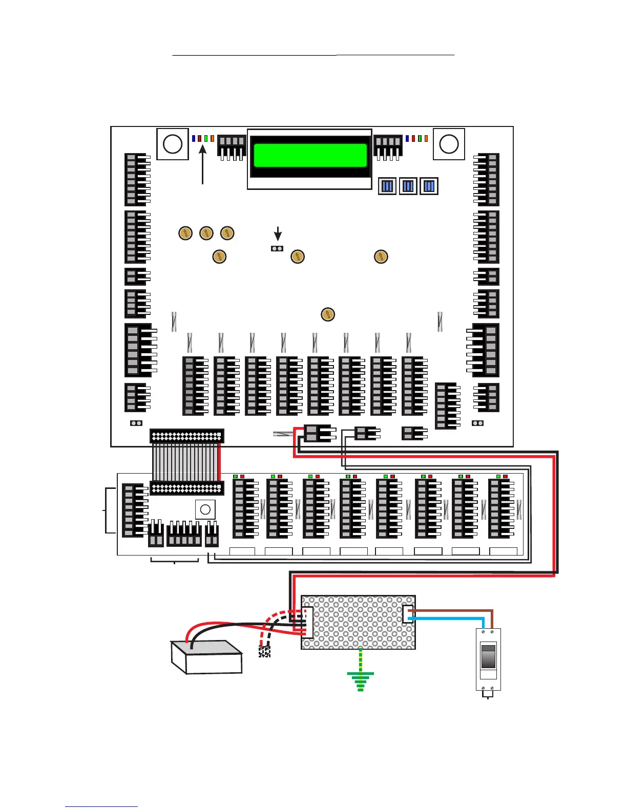
Overall Schematic (Using ENT07101 Rev 3)
Page 3
16 x 2 LCD Module
for Trade Clock Setting
Prog Right UP
SN SB DO CA
Door ‘B’
Connections
Door ‘A’ Connections
RG59 to
Camera
RG59 to
Camera
2 AMP
Delay
500mA
Fast Blow
Handset Fuses 500mA Fast Blow
500mA
Fast Blow
500mA
Fast Blow
500mA
Fast Blow
500mA
Fast Blow
500mA
Fast Blow
500mA
Fast Blow
500mA
Fast Blow
2 AMP
Delay
3.15 AMP
Delay
12V
0V
PL1
PL2
PL3
PL4
PL5
PL6
PL8
PL12
PL21
PL25
PL29
PL30
PL31
PL32
PL28
PL24
PL22
PL20
PL18
PL16
PL15
PL13PL11PL10
PL17
V+
V-
0v
ETC
PL19
PL23
Speech
Time
Callup
Time
Call Tone
Time
Reassurance
Volume
Door A
Lock Timer
Door B
Lock Timer
Common Bus
PL7
PL14
DR
VT
0V
BZ
S2
S1
DS
V-
V+
DR
VT
0V
BZ
S2
S1
DS
FS1 FS11
Re-Assurance LED’s
Showing system status
Video Adj.
Trade Clock Link
Remove if using
external timer
PL7 & 27 =
Anti-tailgating
Link. Remove
to use ATG
connection.
PL7 & 27 =
Anti-tailgating
Link. Remove
to use ATG
connection.
EliteMAN0113/ 3 of 12
Terminal Identifier:-
PL1, 2, 29 & 30 - Button returns/call lines 1 to 16 for doors A & B. Sit at 5 volts DC and go to 0v when button pressed.
PL3 & 31 (S) - Service/Trades (S) button returns for doors A & B. Sit at 5 volts DC and go to 0v when button pressed.
PL3 & 31 (C) - Button common sits at 0v.
PL4 & 32 - Speaker amp connections for doors A & B. +6 = 6 volts DC, 0v = 0v. S1 = door panel microphone, S2 = door panel speaker.
PL6 & 28 (12v) - 12 volts DC supply to locks fused by FS1 & FS11. Use 1.5mm flex
PL6 & 28 (NC) - Normally Closed switched 0v for fail open releases. Use 1.5mm flex
PL6 & 28 (NO) - Normally Open switched 0v for fail locked releases. Use 1.5mm flex
PL6 & 28 (C, NC & NO) - volt free spare contacts to trigger automatic doors etc.
PL5 & 33 (C) - 0v common for external lock triggers.
PL5 & 33 (FS) - Non timed fire switch input (for timed input when using Drop key switches use PE). Sits at 5 volts and drops to 0v.
PL5 & 33 (PE) - Timed lock release trigger for push to exits, drop key fire switches and access controllers. Sits at 5 volts and drops to 0v.
PL5 & 33 (AT) - Anti tail gating. Requires normally open going closed door monitor contacts. Sits at 0v and goes to 5 volts when door opened.
If not used insert PL7 & 27.
PL14 - Service/Trades timeclock link. Remove if using external timeclock.
PL17 - 12 to 14 volt DC power supply input.
PL19 - Twisted pair video output to expansion PCB’s etc.
PL23 - External service/trades time clock input. Note: remove PL14 to disable internal time clock.
PL24 - Common bus to remote marshalling PCB’s. DR = Door Release, VT = 12 volt DC supply, 0v = 0v, BZ = buzz tone, S2 = mic input
from handset, S1 = speaker input to handset, DS = Door Status for door open LED on handset.
PL10, 11, 13, 15, 16, 18, 19, 20 & 22 - Phone ports for first 8 handsets. See Page 6 for handset connections.
PL8 & 25 - Video inputs from cameras. Use RG59 screened cable.
PL12 & 21 - MLR connections to door panel MLR PCB’s. SN = Speak Now, SB = System Busy, DO = Door Open & CA = Call Accept
NOTE:- Cables colour coded for suggested installation wiring. Note all cables CW1308 unless stated otherwise.
2
2
2
1
2
3
4
5
6
7
8
9
10
11
12
13
14
15
16
S
C
+6V
0V
S1
S2
12V
NC
NO
C
NC
NO
C
FS
PE
AT
PL33
PL27
SN SB DO CA SN SB DO CA
9
10
11
12
13
14
15
16
S
C
+6V
0V
S1
S2
12V
NC
NO
C
NC
NO
C
FS
PE
AT
-
+
Battery
1
2
3
4
5
6
7
8
DR
VT
0V
BZ
S2
S1
DS
V-
V+
CB
X
CALL CALL CALL CALL CALL CALL CALL CALL
FUSED FUSED FUSED FUSED FUSED FUSED FUSED FUSED
12V
0V
DS S2S1
BZ
DR
V- V+
Phone 9 Phone 10 Phone 11
Phone 12 Phone 13
Phone 14 Phone 15
Phone 16
No
Connections
Required as
Ribbon Cable
Connects
No Connections Required
as Ribbon Cable Connects
Handset Fuses 500mA Fast Blow
Spare
DC output
ON
MCB
240~ Input
Page 4
Typical Controller Layout (Using ENT07101 Rev 3)
16 x 2 LCD Module
for Trade Clock Setting
Prog Right UP
SN SB DO CA SN SB DO CASN SB DO CA SN SB DO CA
1
2
3
4
5
6
7
8
9
10
11
12
13
14
15
16
S
C
+6V
0V
S1
S2
12V
NC
NO
C
NC
NO
C
FS
PE
AT
1
2
3
4
5
6
7
8
9
10
11
12
13
14
15
16
S
C
+6V
0V
S1
S2
12V
NC
NO
C
NC
NO
C
FS
PE
AT
2 AMP
Delay
500mA
Fast Blow
Handset Fuses 500mA Fast Blow
500mA
Fast Blow
500mA
Fast Blow
500mA
Fast Blow
500mA
Fast Blow
500mA
Fast Blow
500mA
Fast Blow
500mA
Fast Blow
2 AMP
Delay
3.15 AMP
Delay
12V
0V
PL1
PL2
PL3
PL4
PL5
PL6
PL8
PL12
PL21
PL25
PL29
PL30
PL31
PL32
PL28
PL33
PL24
PL22
PL20
PL18
PL16
PL15
PL13PL11PL10
PL17
V+
V-
0v
ETC
PL19
PL23
Speech
Time
Callup
Time
Call Tone
Time
Reassurance
Volume
Door A
Lock Timer
Door B
Lock Timer
Common Bus
PL27PL7
PL14
DR
VT
0V
BZ
S2
S1
DS
V-
V+
DR
VT
0V
BZ
S2
S1
DS
FS1 FS11
Re-Assurance LED’s
Showing system status
Video Adj.
Trade Clock Link
Remove if using
external timer
EliteMAN0113/ 4 of 12
PSU60W Shown. Power supply may vary. 60W Power supplies
Post January 2011 have fixed 13.8v output and no spare
output. PSU Chassis is now Earthed.
Example of typical Elite controller layout. Parts and
models may vary.
1
2
3
4
5
6
7
8
WE/BE
BE/WE
WE/OE
OE/WE
WE/GN
GN/WE
WE/BN
BN/WE
WE/GY
GY/WE
RD/BE
BE/RD
RD/OE
OE/RD
RD/GN
GN/RD
RD/BN
BN/RD
NC
OE/WE+WE/GN+WE/BN
BN
BE
GN/WE
BN/WE
WE/BE+BE/WE+WE/OE
1 Amp
Fit In-Line
Fuse if
SBD
WE/GY
GY/WE
RD/BE
BE/RD
2
1.5mm Flex
WE/GY
GY/WE
RD/BE
BE/RD
SN SB DO CA
WE/BE
BE/WE
WE/OE
WE/BE
BE/WE
WE/OE
OE/WE
WE/GN
GN/WE
WE/BN
BN/WE
WE/GY
GY/WE
RD/BE
BE/RD
RD/OE
OE/RD
RD/GN
GN/RD
RD/BN
BN/RD
NC
GN/WE
BN/WE
OE/WE+WE/GN+WE/BN
WE/BE+BE/WE+WE/OE
Fit In-Line
Fuse if
SBD
BN
BE
 Loading...