Typical Installation Layout
Page 5
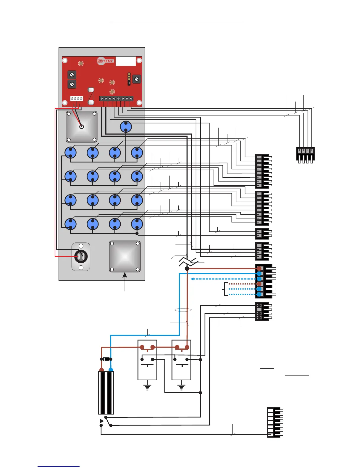
1
2
3
4
5
6
7
8
9
10
11
12
13
14
15
16
S
C
+6V
0V
S1
S2
12V
NC
NO
C
NC
NO
C
FS
PE
AT
PL1
PL2
PL3
PL4
PL5
PL6
SN
SB DO
CA
PL12
P4
P3
P2
P1
Please Note:-
FS is a none timed
input and is suitable
for Latching Fire
switches such as the
MEM type lever fire
switch.
NO
NO
NCNC
Fire
Switch
Push to
Exit
Magnetic or Fail
Open Release
1N4000
Series
Diode
Fail Secure Lock
Connection
Spare
Contacts
NC
NO
To PL24 DS on common bus terminal
PL24
Common Bus
DR
VT
0V
BZ
S2
S1
DS
Note:-
Magnetic lock door contacts
CAN NOT be used for ATG
function as these locks now
monitor power to the lock
and not door status
ENT11130A
Part Number:
ASS11130A1
Elite LCD
12v 0v S1 S2 SN SB DO CA
-
+
-
+
Speaker Microphone
TP1
5vA
TP2
12v
TP3
5vD
TP4
0v
Speaker
Volume
PR1
PR3
Microphone
Volume
LCD
Contrast
PR2
1 Amp
Fuse
PL2 PL1
FS1
PL3
See Note A
Note A: Please note if system
is to conform to Secured By
Design standards then a 1A
in-line fuse must be fitted here.
Lock & trigger wires must not
be routed via the door panel.
P8
P7
P6
P5
P12
P11
P10
P9
P16
P15
P14
P13
T
Proximity
Reader
Mic
WE/BE
BE/WE
WE/OE
OE/WE
WE/GN
GN/WE
WE/BN
BN/WE
WE/GY
GY/WE
RD/BE
BE/RD
RD/OE
OE/RD
RD/GN
GN/RD
BN/RD
RD/BN
NC
2
1.5mm Flex
OE/WE+
WE/GN+
WE/BN
WE/BE+
BE/WE+
WE/OE
Connections as per
Manufacturers Inst.
GN/WE BN/WE
WE/BE
BE/WE
WE/OE
OE/WE
BN
BE
BE/RD
RD/BE
GY/WE
WE/GY
EliteMAN0113/ 5 of 12
EliteMAN0113/ 6 of 12
Page 6
Handset Connections
DR
VT
0V
BZ
S2
S1
DS
Do Not Wire To EX With Spare Core(s)
PL10
ED3+ ED4+,& RH3+
Wiring Schematic
White/Blue
Blue/White
White/Orange
Orange/White
White/Green
Green/White
White/Brown
1(DR)
2(VT)
3(0V)
4(BZ)
5(S2)
6(S1)
7(DS)
ON
PRIVACY
ON
PRIVACY
4 Pair CW1308 Colour Code
PL10
DR (Door Release)
VT (12v DC)
0V (0 Volts)
BZ (Buzz input)
S2 (Mic)
S1 (Speaker)
DS (Door Status)
V- (TP Video -)
V+ (TP Video +)
White/Blue + Blue/White
White/Orange + Orange/White
White/Green + White/Brown
White/Grey
Green/White
Brown/White
‘EX’ To Extension Sounders/
Flashing Beacons Only
6 Pair CW1308 Colour Code
Grey/White
Red/Blue
Blue/Red
Note:- Spare Blue / White shown in ‘DR’ may be
used to ‘Double-Up’ on VT or 0V if needed.
DR
VT
0V
BZ
S2
S1
DS
V-
V+
CB
X
EX
Entroview 300 / 400
Wiring Schematic
NOTE - The EX
connection is ONLY
to be used on
Entrotec Extension
sounders and
accessories. DO
NOT fit a wire into
EX for any other
purpose.
Any unused cores to be tied to
system 0v.
ONLY USE
CW1308 CABLE
PL10
Multiple ED3+ ED4+ & RH3+
Wiring Schematic (up to 3).
White/Blue
Blue/White
White/Orange
Orange/White
White/Green
Green/White
White/Brown
1(DR)
2(VT)
3(0V)
4(BZ)
5(S2)
6(S1)
7(DS)
ON
PRIVACY
ON
PRIVACY
4 Pair CW1308 Colour Code
1(DR)
2(VT)
3(0V)
4(BZ)
5(S2)
6(S1)
7(DS)
ON
PRIVACY
ON
PRIVACY
8(EX)
1(DR)
2(VT)
3(0V)
4(BZ)
5(S2)
6(S1)
7(DS)
8(V-)
9(V+)
1(DR)
2(VT)
3(0V)
4(BZ)
5(S2)
6(S1)
7(DS)
8(V-)
9(V+)
DR
VT
0V
BZ
S2
S1
DS
V-
V+
CB
X
EX
DR
VT
0V
BZ
S2
S1
DS
V-
V+
CB
X
EX
Spare port
supplies
12v & Video
1 port per
additional
handset reqd.
Handset port where call
is made to e.g. Phone 1
with 2 video handsets.
Mulitple Video
Handsets per call
(up to 3)
Separate Door Contacts
White/Blue + Blue/White
White/Orange + Orange/White
White/Green + White/Brown
White/Grey
Green/White
Brown/White
Grey/White
Blue/Red
Red/Blue
White/Blue + Blue/White
White/Orange + Orange/White
Blue/Red
Red/Blue
Orange/White