11 12
Step 7: Mount EnverBridge
Step 8:Prepare AC extension cable
It is suggested to use extension cable of AWG12 above (same or higher than Envertech AC cable
standard).
1. Remove the skin of the two ends of the extension cable by y=40mm and remove the skin of internal
wires by x=14mm. Set the metal terminal onto the open parts and clamp them to tighten the connection;
2. Connect one side of the extension cable to the junction box;
3. Connect the other side of the extension cable to the air switch.
Step 9:Connect PV modules to microinverters
Mount the PV modules on top of microinverters;
Connect each PV module with the DC input cables of the microinverters.
Please notice the symbols.
7.1 Energize the System
1)Turn on the switch or the circuit breaker at each microinverter AC branch.
2)Turn on the main AC circuit breaker in the distribution box. Your system will start
to produce power after 3 minutes.
Step 10: Switch on the PV system
Ensure all connection is completed and then turn on the air switch.
Option 1: Indoor installation(I)
1.Turn o the air switch and connect EnverBridge to
the socket. This operation should be done under the
instruction of professionals.
2.Fix EnverBridge at proper position in or close to the
distribution box;
3. Open the cover on the right side of EnverBridge.
Run the RJ45 cable through the waterproof connec-
tor and connect it to the network input. Close the
cover and recheck if it’s completely sealed;
4. Run the RJ45 cable and connect the other side to
your router;
5. Put the EnverBridge plug into the socket.
Option 2: Indoor installation(II)
1. Open the cover on the right side of
EnverBridge. Run the RJ45 cable through the
water proof connector and connect it to he
network input. Close the cover and recheck if it’s
completely sealed;
2. Run the RJ45 cable and connect it to your
router;
3. Fix EnverBridge at proper position in or close to
the distribution box;
4. Turn o the air switch and connect
EnverBridge’s power cable to the air switch.
This operation should be done under the instruc-
tion of professionals.
1 2 3
7. Debugging and Operating
Only qualied personnel may connect the Envertech microinverter to
the utility grid after receiving prior approval from the electrical utility
company.
!
WARNING
Ensure that all AC and DC wiring is correct.
Ensure that none of the AC and DC wires is twisted or damaged.
!
WARNING
x=14mmR
AC Extension Cable
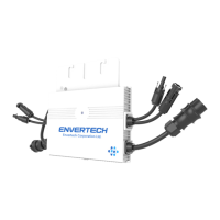
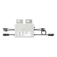
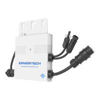
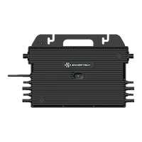
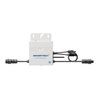
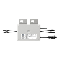
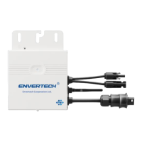
PV Microinverter
Model
:EVT1200
Zhejiang Envertech Corporation Lt d.
www.envertec.com
Operating range (Vdc):
MPPT Voltage Range (Vdc):
Max. DC input (Vdc):
Max. input current (A):
Isc PV (Absolute Max.) (A) :
Enclosure rating:
Power (Max. continuous) (W):
Operating temperature range:
Normal Output Voltage (Vac):
Current (Max. continuous) (A):
Nominal Output frequency:
Power factor:
Maximum units per branch:
Protecti
ve class:
Overvoltage category:
18V~54V
24V~45V
54V
12Ax4
15A
IP67
-40
℃ ~ +65℃
1200W
��������
5.45A
��������
>0.99
5
I
III[Mains],II[PV]
User Identification Number: