16
Installation
QUALIFIED INSTALLERS ONLY
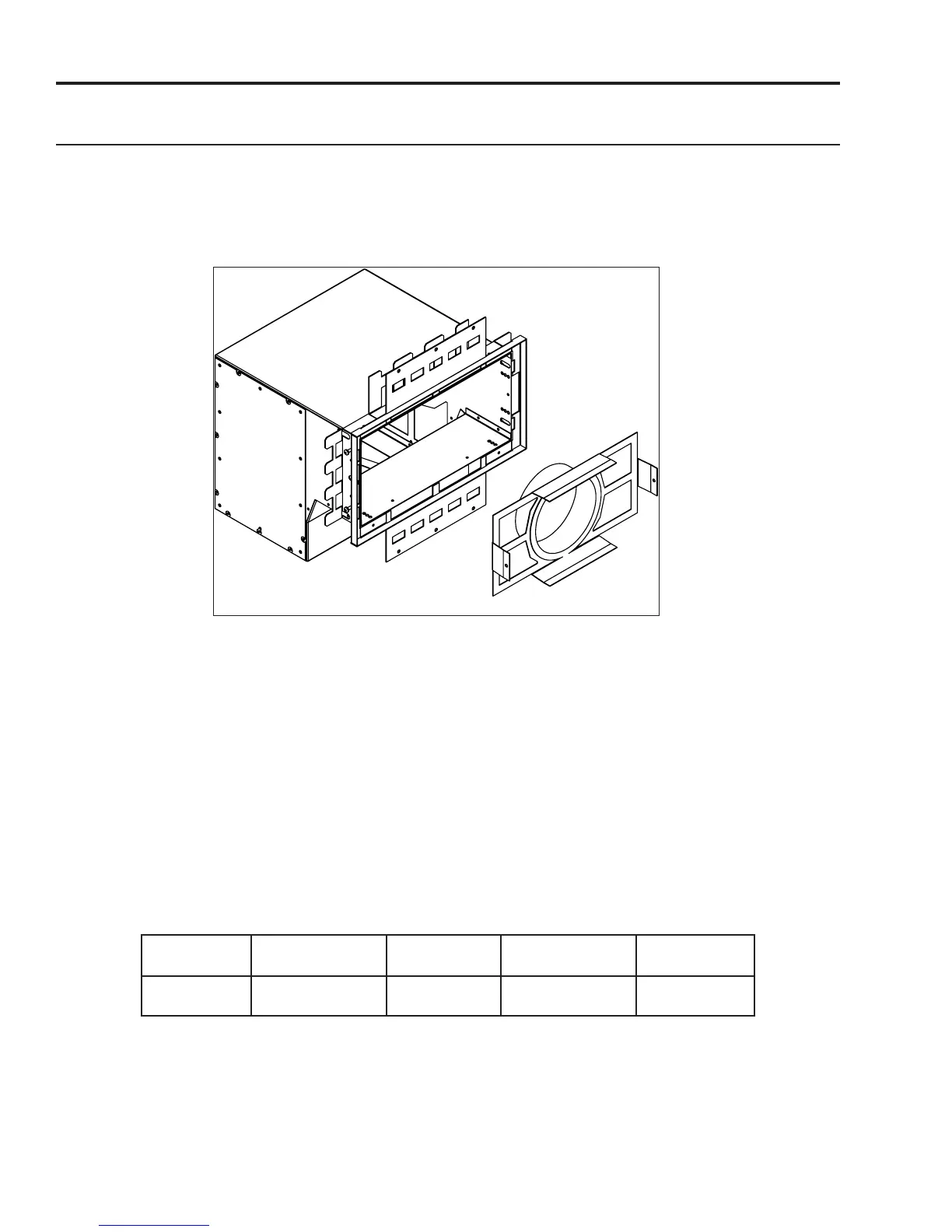
Step 8: Connect the required lengths of 5” dia. stainless steel or aluminium ex vent (not supplied)
to the duct collar registers. Secure the venting to the collars using either sheet metal screws or band
clamps. Both side vents of the CSS must be connected to the replace via 5” dia. ex vent.
Feed the ex vent through the CSS Side vent body. This will facilitate instalation.
side vent:
Figure 23. Flex Vent Connection
Step 9: Push the duct collar register into the side vent body while pulling the ex ent through the
other side. Fasten the duct collar register to the inside of CSS Side by the screws on both sides.
Step 10: Insert the assembled CSS Side Vents into the framed rough opening by rotating them slightly
to allow the side vent bodies to pass through.
Step 11: Conrm the CSS is centered within the rough opening and secure in place using screws or
nails through the four (6) holes along the edges the standoffs.
Step 12: Connect the 5” dia. stainless steel or aluminium ex vent (not supplied) to the unit using
either sheet metal screws or band clamps. Both side vents of the CSS must be connected to the
replace via 5” dia. ex vent.Secure the ex venting where necessary to maintain standard venting
clearances:
Vertical Pipe to
the Side Walls
Horizontal Pipe to
the Sides & Bottom
Above an Elbow
Above the Unit
Above an Elbow
Not Above the Unit
Above Horizontal
Vent Pipe
1”
(25.4 mm)
1”
(25.4 mm)
3”
(76.2 mm)
3”
(76.2 mm)
2”
(51 mm)
Step 13: Replace the grill and bezel in reverse order of their removal. The grill and bezel can be
painted to match the colour of the wall if desired (must be hi-temperature rated).
Note: Flex venting must be non-insulated and listed to UL 1777 and ULC S635 standards
 Loading...