JOHNSON CONTROLS
11
FORM ET115.24-NOM5 (908)
Submittals and Product Catalogs detailing unit operation,
controls, and connections should be thoroughly
reviewed BEFORE beginning the connection of the
various cooling and/or heating mediums to the unit.
All accessory valve packages should be installed as
required, and all service valves should be checked for
proper operation.
If coil and valve package connections are to be made
with “sweat” or solder joint, care should be taken to
assure that no components in the valve package are
subjected to a high temperature which may damage seals
or other materials. Many two-position electric control
valves, depending on valve operation, are provided with
a manual-opening lever. This lever should be placed
in the “open” position during all soldering or brazing
operations. Valve bodies should be wrapped with a wet
rag to help dissipate heat encountered during brazing.
If the valve package connection at the coil is made with
a union, the coil side of the union must be prevented
from twisting (“backed up”) during tightening to prevent
damage to the coil tubing. Over-tightening must be
avoided to prevent distorting the union seal surface and
destroying the union. In the case of eld installed valves
and piping, the chilled water valve cluster (or expansion
valve on DX units) should be installed in such a way that
any dripping or sweating is contained in the auxiliary
drain pan or other device. Valves and TXV’s should be
secured or supported to avoid damage to coil headers
or distributor tubes.
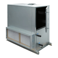
AUXILIARY DRAIN PANS
Mounted directly to the unit drain pan, AUXILIARY
DRAIN PANS may also be secured by the mounting
holes to eld supports or to the unit coil utilizing pipe
hanger wire, plastic ties, or metal strapping.
After the connections are completed, the system should
then be tested for leaks. Since some components are not
designed to hold pressure with a gas, hydronic systems
should be tested with water.
All water coils must be protected from
freezing after initial lling with water.
Even if the system is drained, unit coils
may still hold enough water to cause
damage when exposed to temperatures
below freezing.
Refrigerant systems should be tested with dry nitrogen
rather than air to prevent the introduction of moisture
into the system. In the event that leaking or defective
components are discovered, the Sales Representative
must be notied BEFORE any repairs are attempted.
All leaks should be repaired before proceeding with
the installation.
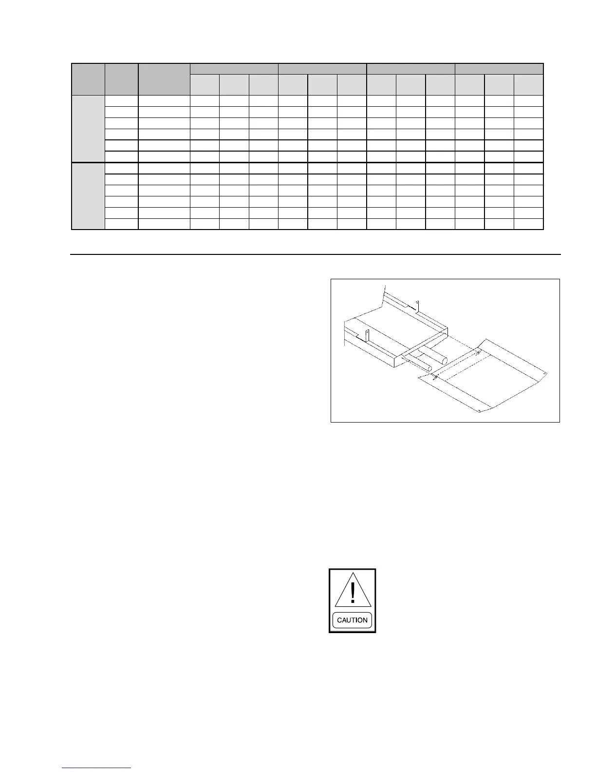
QS
(MBH
)
QS
(MBH
)
QS
(MBH
)
QS
(MBH
)
GPM WPD GPM WPD GPM WPD GPM WPD
20 250 8.6 0.4 0.2 15.7 0.8 0.9 19.7 1.0 0.3 22.9 1.2 0.5
25 400 15.0 0.6 0.6 21.0 1.1 3.1 30.0 1.5 1.1 28.3 1.4 1.8
HLP 30 500 16.1 0.8 0.6 29.2 1.5 3.2 38.3 2.0 1.2 43.4 2.2 0.7
HLF 40 750 23.6 1.2 1.5 40.5 2.1 1.6 55.2 2.8 1.1 64.9 3.3 1.8
50 1000 28.7 1.5 0.7 53.7 2.7 2.9 73.7 3.8 2.0 86.5 4.4 3.4
60 1400 36.1 1.9 1.1 66.9 3.4 4.7 92.4 4.7 3.4 108.3 5.5 5.6
20 250 7.9 0.4 0.3 14.0 0.8 1.5 19.2 1.0 0.5 17.4 0.9 0.8
25 350 10.8 0.6 0.5 19.3 1.0 2.6
27.2 1.4 0.9 25.4 1.3 1.5
30 450 13.5 0.7 0.9 24.0 1.3 4.8 30.7 1.6 1.7 34.4 1.8 1.0
40 650 20.4 1.1 2.0 34.0 1.8 1.7 46.0 2.4 1.2 49.6 2.6 1.9
50 850 22.5 1.2 0.7 40.7 2.1 3.1 53.0 2.8 2.1 59.4 3.0 3.3
60 1200 30.9 1.6 1.2 55.4 2.9 5.5 72.6 3.8 3.9 80.0 4.1 6.0
2 ROW 3 ROW 4 ROW
HLE
UNIT
TYPE
UNIT
SIZE
NOM INAL
CFM
1 ROW
NOTE: Based on 70°F DB EAT, 180°F EWT, 40°F temperature drop, high
fan speed.
HEATING CAPACITY
LD13888
LD13889