7
www.ewswater.com O: 702.256.8182; M-F 8:30am-4:30pm PST E: customerservice@ewswater.com
Placement/Where to Install the Water System
Simply place the water system on a level oor, cabinet bottom or horizontal surface.
Always assume for enough space and tubing to remove, move and/or adjust the system
for lter replacement and maintenance.
If mounting the system to a wall, cabinet side or other vertical surface, a minimum clearance of 4” will be required to allow for
lter replacement. Please see the following procedures:
Step 1
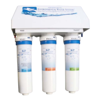
All lter cartridges for the system are included. For Model # DWS-UV only, UV Lamp and Housing are pre-installed.
Locate the 3 lter cartridges. Starting from the left or “FEED” side, Stage 1 insert the blue labeled pre-sediment lter, next
Stage 2 insert the orange labeled pre-lter and lastly Stage 3 insert green post-lter.
Inserting the lter cartridge:
At the blue top of each lter cartridge nd the side with two (2) notches. Line the notches up and insert lter cartridge into
the lter head assembly. Once cartridge is fully inserted into the head turn clockwise and completely lock into position.
NOTE: Water ows from Left (Labeled: FEED) to Right (Labeled FAUCET)
Filters (by color) from Left to Right: Blue, Orange, Green
Step 2
Once lter system has been fully assembled, mark pilot holes using the bracket as a template.
Step 3
Using a drill bit or punch, drill a hole or punch as a starter hole to catch the mounting screws.
WARNING: ALTERNATIVE FASTENING METHOD MAY BE REQUIRED FOR PLASTER BOARD, PARTICLE BOARD OR SIMILAR MATERIAL
INSTALLATION. USE SAFETY GLASSES OR OTHER EYE PROTECTION TO PREVENT POSSIBLE EYE INJURY DUE TO FLYING PARTICLES.
Step 4
Set mounting screws (provided) with screw driver. Leave a 1/4” gap between the screw head and mounting surface to allow
the bracket to slide on easily.
Step 5
Slide the bracket over the screws and hang the unit. Make sure unit is level. Now make the connections of tubing to/from the
system.
Helpful Hint:
Take a note of the Model # for the required
warranty registration of this unit. This Service
Guide will come in very handy when it’s time
for lter replacement.
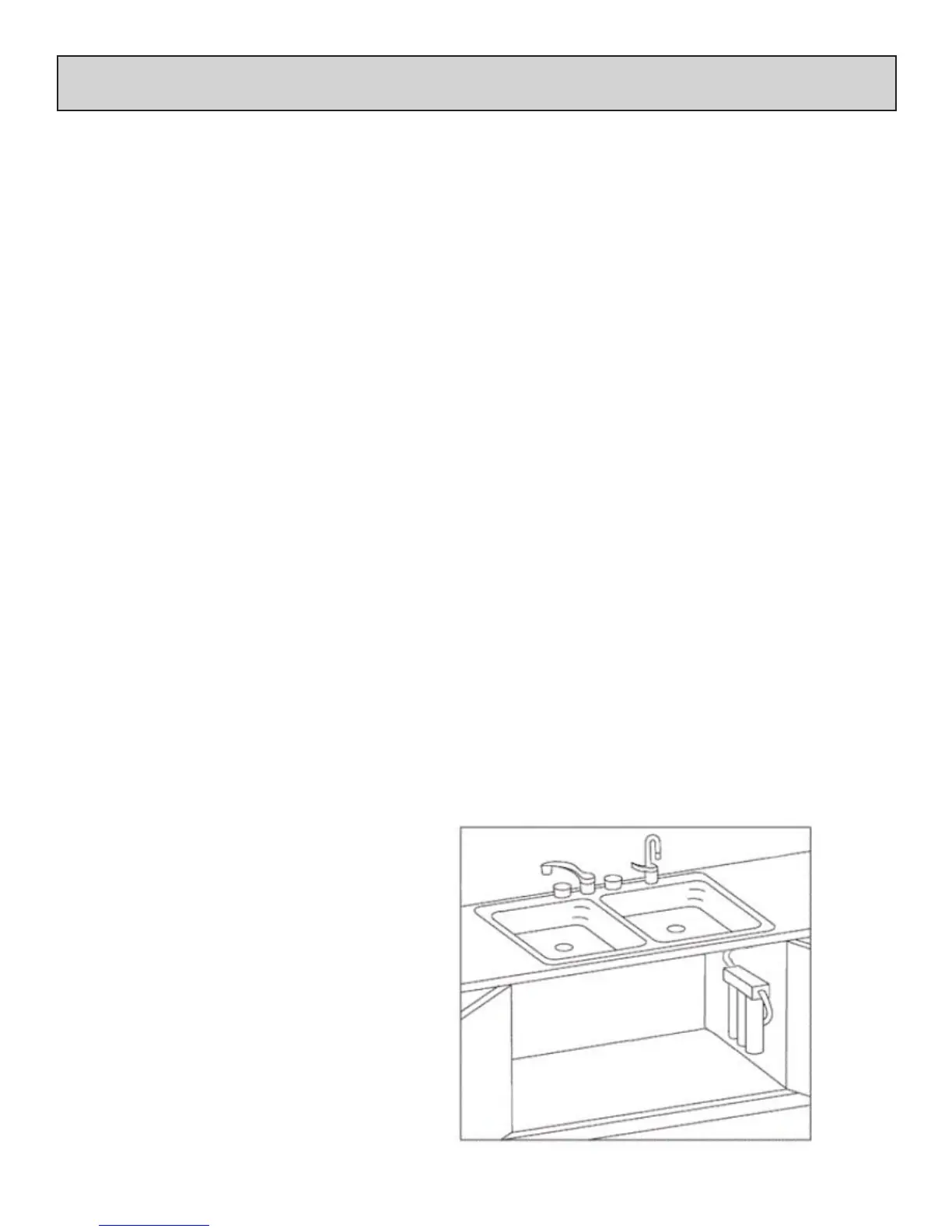
Kitchen Faucet
Dispenser/Faucet of
ltered water
Inlet from
Cold
Inlet/Supply
Connection
(angle stop
not shown)
strictly for illustration purposes only
Unit Mounted to Wall (option shown) or
Placed on level oor
Please Note:
Water ows from Left (Labeled: FEED)
to Right (Labeled FAUCET)
Filters (by color) from Left to Right:
Blue, Orange, Green
 Loading...