assembly/installation procedure
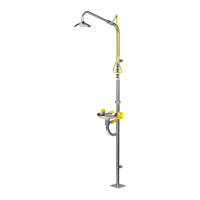
1. Place the unit so there is enough space for any addional
plumbing xtures being used (drain, taps, strainers,
shut-o valves). Bolt base of Lower Shower Assembly to a level
oor using 4 corrosion resistant anchors (see AS/NZS 2982.1,
ANSI Z358.1-2009 and AS/NZS4775-2007).
Base Plate is 150mm square with mounng holes at 100mm
centres. SEE IMAGE 1.
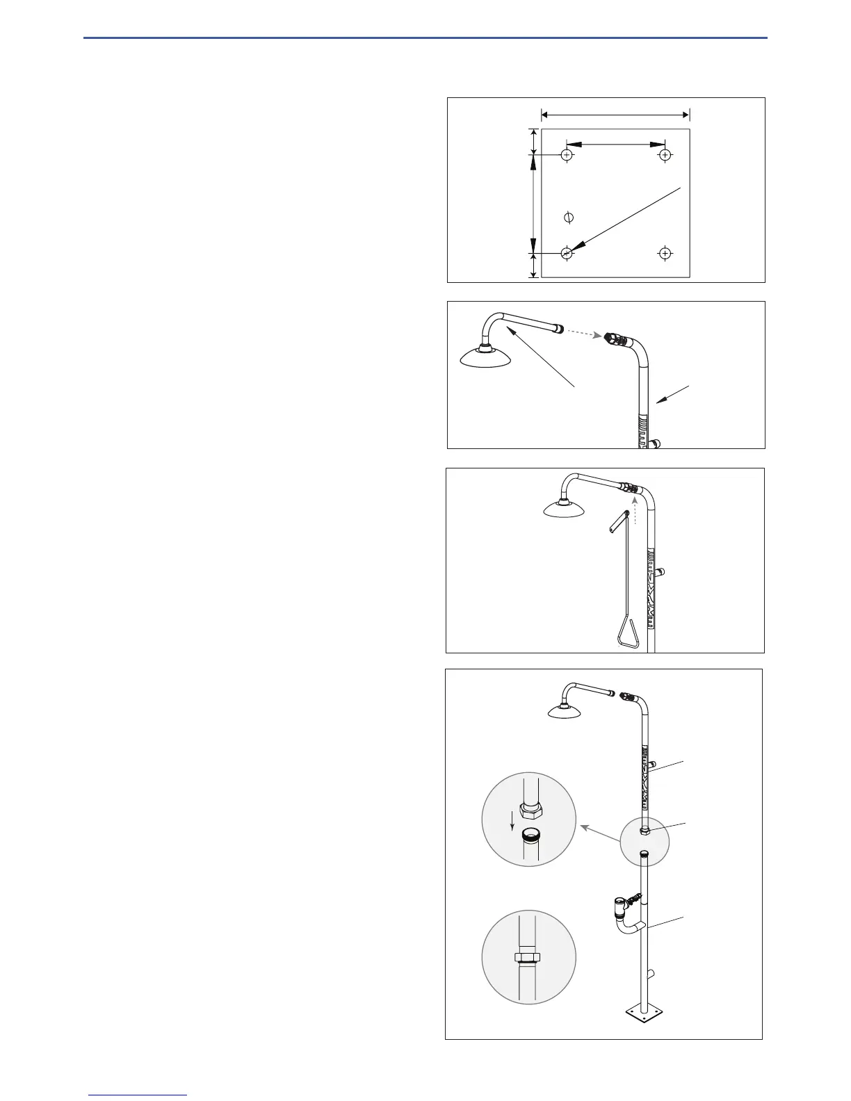
2. Apply sealing tape or Locte 577 to threaded end of shower rose
assembly and screw it into the ball valve of the Upper Shower
Assembly. SEE IMAGE 2. Tighten to an aligned posion where
the shower head is parallel to the oor.
3. Aach the pull arm to the Upper Ball Valve using the nut already
on the ball valve. SEE IMAGE 3. The valve arm should point up at
45 degrees when in the o posion.
4. Connect Upper Shower Assembly to Lower Shower
Assembly using the integral Stainless Steel Union.
SEE IMAGE 4. No tools are required.
Be sure the rubber O-ring is in place on the tapered secon of
the union and ghten by hand. For combinaon showers, make
sure the arm of the shower is centered over the Eye (Eye/Face)
wash.
100 TYP
100 TYP
11.1 TYP - CLIENT
TO SUPPLY BOLTS
TO SUIT
150mm
25
25
IMAGE 1
Upper Frame
Shower Arm and Rose
IMAGE 2
Upper Frame
Base Frame
Stainless Steel
Union
Place upper part onto
lower part vertically align,
then tighten the union.
IMAGE 4
IMAGE 3
 Loading...