Resistors are used, in this
case, to increase eciency of
data transmission and reduce
any possibility of noise and
interference.
Considerations should be
observed when creating your
serial line topology.
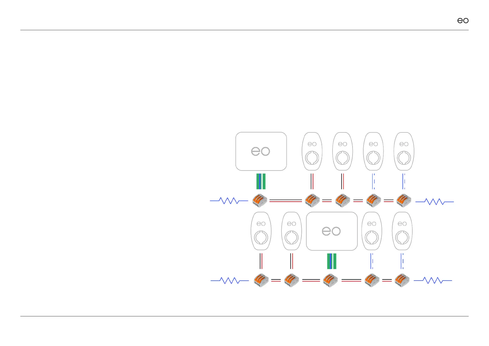
Both examples opposite are
correct due to the placement of
both termination resistors.
In both examples, resistors are
placed at both ends of the serial
line.
Resistors should bridge both
comms A & B wires.
3.07
To ensure a reliable
communication on the RS485
serial cable, a 120 ohm 0.25W
terminating resistor must be
tted at each end of the serial
line, eectively bridging both
serial wires.
EO Genius & EO Hub Installation Guide
© EO Charging 2021 18
3.0
Resistors for the
Serial Bus RS485.
Figure 9