BEIJING EPSOLAR TECHNOLOGY CO., LTD. Tel:+86-10-82894112 / 82894962 Website:www.epsolarpv.com/www.epever.com
1 2
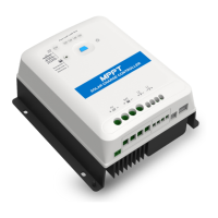
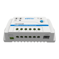
LandStar B series
——Solar Charge Controller
1 Overview
LandStar B series is a PWM common positive solar charge controller that adopts the most
advanced digital technique. The multiple load control modes enable it can be widely used
on solar home system, traffic signal, solar street light, solar garden lamp, etc. The features
are listed below:
Features:
Adopt high quality components of ST,IR and Infineon, make sure product lifespan
Terminals have UL and VDE certification, the product is more safer and more reliable
100% input and output in the environment temperature range
3-Stage intelligent PWM charging:Bulk, Boost/Equalize, Float
Support 3 charging options: Sealed, Gel, Flooded and User
RS485 communication interface and Modbus communication protocol
Battery temperature compensation function
Energy statistics function
Multiple load control modes
Extensive Electronic protection
2 Product Features
Remote Temperature(RTS)Port
★
★If the temperature sensor is short-circuited or damaged, the controller will charge
or discharge at the default temperature setting of 25 ºC.
3 Wiring
Installation Procedure:
Connect the system in the order of ❶battery ❷ load ❸PV array in
accordance with Figure 2”Connection diagram” and disconnect the system in the reverse
order❸❷❶.
NOTE: The LS-B series is a positive ground controller. Any positive
connection of solar, load or battery can be earth grounded as required.
NOTE:While wiring the controller do not close the circuit breaker or fuse
and make sure that the leads of "+" and "-" poles are connected correctly.
NOTE: A fuse which current is 1.25 to 2 times the rated current of the
controller must be installed on the battery side with a distance from the
battery not greater than 150 mm.
NOTE: If an inverter is to be connected to the system, connect the inverter
directly to the battery, not to the load side of the controller.
4 Indicator and button
(1)Indicator
PV connection normal ,but
low voltage(low irradiance)
from PV, no charging
No PV voltage(night time)
or PV connection problem
Charge, Load and Battery(orange)indicator flashing
Charge, Load and Battery(red)indicator flashing
(2)Button
①The load is turned ON/OFF via the button when the working mode is Manual Control.
②Clear the faults for the load overload and short circuit .
5 Setting
❶ USB to RS485 converter cable: CC- RS485-RS485-150U
PC software website: www.epever.com(PC Software for the Solar Charge Controller)
❷ USB to RS485 converter cable: CC- RS485-RS485-150U
OTG cable: OTG-12CM
Phone APP software website (support Andriod system only)
www.epever.com(Andriod APP for the Solar Charge Controller)
❸ USB to RS485 converter cable:CC-RS485-RS485-200U-MT)
(1)Battery types
Battery Voltage Control Parameters
Below parameters are in 12V system at 25 ºC, please double the values in 24V system
Over Voltage Disconnect Voltage
Over Voltage Reconnect Voltage
Equalize Charging Voltage
Boost Reconnect Charging Voltage
Low Voltage Reconnect Voltage
Under Voltage Warning Reconnect
Voltage
Under Voltage Warning Voltage
Low Voltage Disconnect Voltage
Discharging Limit Voltage
NOTE:
1) When the battery type is sealed, gel, flooded, the adjusting range of equalize duration is
0 to180min and boost duration is 10 to180min.
2) The following rules must be observed when modifying the parameters value in user
Figure 2 Connection diagram
※Thank you for selecting the LandStar B series solar charge controller.
Please read this manual carefully before using the product and pay attention
to the safety information.