EasyManua.ls Logo

Epever MT52 - User Manual

Epever MT52
44 pages
Print Icon
To Next Page IconTo Next Page
Loading...
Remote Meter
User Manual
MT52
Question and Answer IconNeed help?

Do you have a question about the Epever MT52 and is the answer not in the manual?

Overview

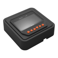
The EPEVER MT52 is a remote meter designed to monitor and program solar charge controllers equipped with RS485 communication. It provides real-time system data, allows for browsing and modifying parameters, and supports restoring factory defaults through its LCD and functional keys.

Function Description:

The MT52 serves as a user interface for compatible EPEVER solar charge controllers. Its primary functions include:

  • Real-time Monitoring: Displays various system parameters such as PV voltage and current, battery voltage and current, load voltage and current, charge and discharge energy (daily, monthly, total), battery temperature, maximum and minimum battery voltage, and controller status (e.g., charge status, fault information).
  • Fault Alarms: Provides real-time display of fault alarms, with a dedicated failure indicator on the device. Detailed fault information can be accessed through the "Failure Info" menu.
  • Parameter Programming: Allows users to browse and modify control parameters, load settings, and device parameters of the connected controller.
  • Test Operation: Features a load switch test to verify normal load output without affecting actual working settings.
  • Device Information: Displays the controller's software and hardware versions, device ID, LCD backlight time, and internal clock.
  • Password Protection: Supports setting and modifying a 6-digit password for accessing modification modes for control parameters, load settings, device parameters, and factory reset.
  • Factory Reset: Enables restoring the controller's control parameters, load settings, charge mode, and device password to their factory defaults.

Important Technical Specifications:

  • Communication: RS485 communication via an RJ45 port.
  • Communication Cable: Standard 2m, longest 50m.
  • Self-consumption: Backlight ON < 23mA, Backlight OFF < 15mA.
  • Dimensions:
    • Faceplate: 98mm × 98mm
    • Frame: 114mm × 114mm
    • Overall: 114mm x 114mm x 48.2mm (for frame mount)
    • Mounting: 84mm x 84mm
    • Screw hole: Φ5
  • Environment Temperature: -20°C ~ +70°C.
  • Net Weight: Simple package: 0.23 Kg, Standard package: 0.32kg.
  • RJ45 Pin Definition:
    • Pin 1, 2: +5~12V Power input
    • Pin 3, 4: RS485-B
    • Pin 5, 6: RS485-A
    • Pin 7, 8: GND

Usage Features:

  • Easy Installation and Operation: Designed for straightforward setup and user interaction.
  • Direct Power Supply: Powered directly by the connected controller.
  • User-Friendly Interface: Features an LCD display and six buttons (ESC, Left, Up, Down, Right, OK) for navigation and operation.
  • Main Menu Structure: Organizes functions into categories like Monitoring, Device Info, Test Operation, Control Para, Load Set, Device Para, Device PSW, Factory Reset, Failure Info, and Meter Para.
  • Real-time Monitoring Pages: Offers 13 pages of real-time data, including charge/discharge energy, battery status (voltage, current, temperature, max/min voltage, charge status, energy status, fault), PV status (voltage, current, power, connection status, fault, charge mode), controller status (temperature, status), and load status (voltage, current, power, status, fault, load mode information).
  • Control Parameter Modification:
    • Battery Type: Supports Sealed, Gel, Flooded, Lithium (LiFePO4 and Li(NiCoMn)O2 series), and User-defined battery types. Note that some Lithium battery types (15S/16S, 13S/14S) are only displayed if the controller supports 48V systems.
    • Battery AH, Temp Comp. Coeff, Rated Voltage: Allows setting battery capacity (1-9999Ah), temperature compensation coefficient (0 to -9mV/°C/2V), and rated voltage (Auto/12V/24V/36V/48V).
    • Voltage Parameters: Configurable battery charging and discharging voltage parameters (e.g., Over voltage disconnect, Charging limit, Equalize charging, Boost charging, Float charging, Boost reconnect, Low voltage reconnect, Under voltage warning reconnect, Under voltage warning, Low voltage disconnect, Discharging limit). These values are typically based on 12V/25°C and scale for 24V (double) and 48V (multiply by 4) systems.
    • Equalize/Boost Duration: Adjustable duration for equalize and boost charging (0-180min and 10-180min respectively).
    • Voltage Logic: Specific logical relationships must be maintained between different voltage parameters, especially for "USE" battery types (both Lead-acid and Lithium).
  • Load Setting Modes: Supports four load working modes:
    • Manual Control: Load is ON if battery capacity is sufficient and no abnormal conditions exist; otherwise, OFF.
    • Light On/Off: Load turns ON when PV input voltage is below Light On voltage, battery capacity is sufficient, and no abnormal conditions exist. Load turns OFF when PV input voltage is above Light Off voltage. Includes a "Delay time" for light signal confirmation (0-99mins).
    • Light On+Timer: Load working period after light control turns on (T1) and before light control turns off (T2). "0" means stop working. Real working time of T2 depends on night-time and T1/T2 length. Total night-time is calculated (≥3h).
    • Time Control: Allows setting ON/OFF times for the load through a real-time clock. Supports a compulsory load working time (T1) and an optional second interval (T2) for dual timer function.
  • Meter Parameter Configuration: Allows browsing and modifying meter-specific parameters like automatic page switching interval (Sw-Pages: 0-120S), LCD backlight time (Bklight: 0-999S), and display language (LangSel: Cn/En). A specific button combination (long-press Left + Up + Down + Right) enters the language selection page.
  • Communication Indicator: A dedicated LED indicates the communication status between the MT52 and the connected controller.

Maintenance Features:

  • Fault Information Display: The "Failure Info" page can display up to 15 failure messages from the solar controller. These messages are automatically cleared once the underlying fault is resolved. Common failure types include:
    • Charging device failures: Load MOS-Short, Load Circuit, Load O. cur. (over current).
    • Input failures: Input O. cur. (over current), RPP Short (reverse polarity protection short-circuited), RPP Break (reverse polarity protection breaks), Char. MOS-Short (charge driver short-circuited), No Input Power, Input vol. High, Input vol. Low.
    • Controller failure: Ctrler O. Temp. (over-temperature).
    • Communication failure: Comm. Timeout.
    • Battery failures: Batt. O. Hi. Temp. (over high temperature), Batt. O. Lo. Temp. (over low temperature), Batt. I. R. Eorr (internal resistance error), Rated Vol Err. (rated voltage error), Batt. OVD (over voltage disconnect), Batt. UVW (under voltage warning), Batt. LVD (low voltage disconnect), Batt. Err (battery type error).
  • Warranty Procedure: Users are advised to consult the manual or contact after-sales personnel for fault resolution. If factory maintenance is required, the product should be sent via express delivery with shipping costs prepaid, and a purchase invoice provided for warranty validation. The returned product should include the model number, usage environment data, and a detailed fault description. The warranty does not cover damage due to improper use or failure to follow the user manual. Maintenance costs may apply during the process.

Epever MT52 Specifications

General IconGeneral
BrandEpever
ModelMT52
CategoryMeasuring Instruments
LanguageEnglish

Related product manuals