Instructions
10 © Construction Tools GmbH | 3390 5140 01 | 2020-09-15
Original Instructions
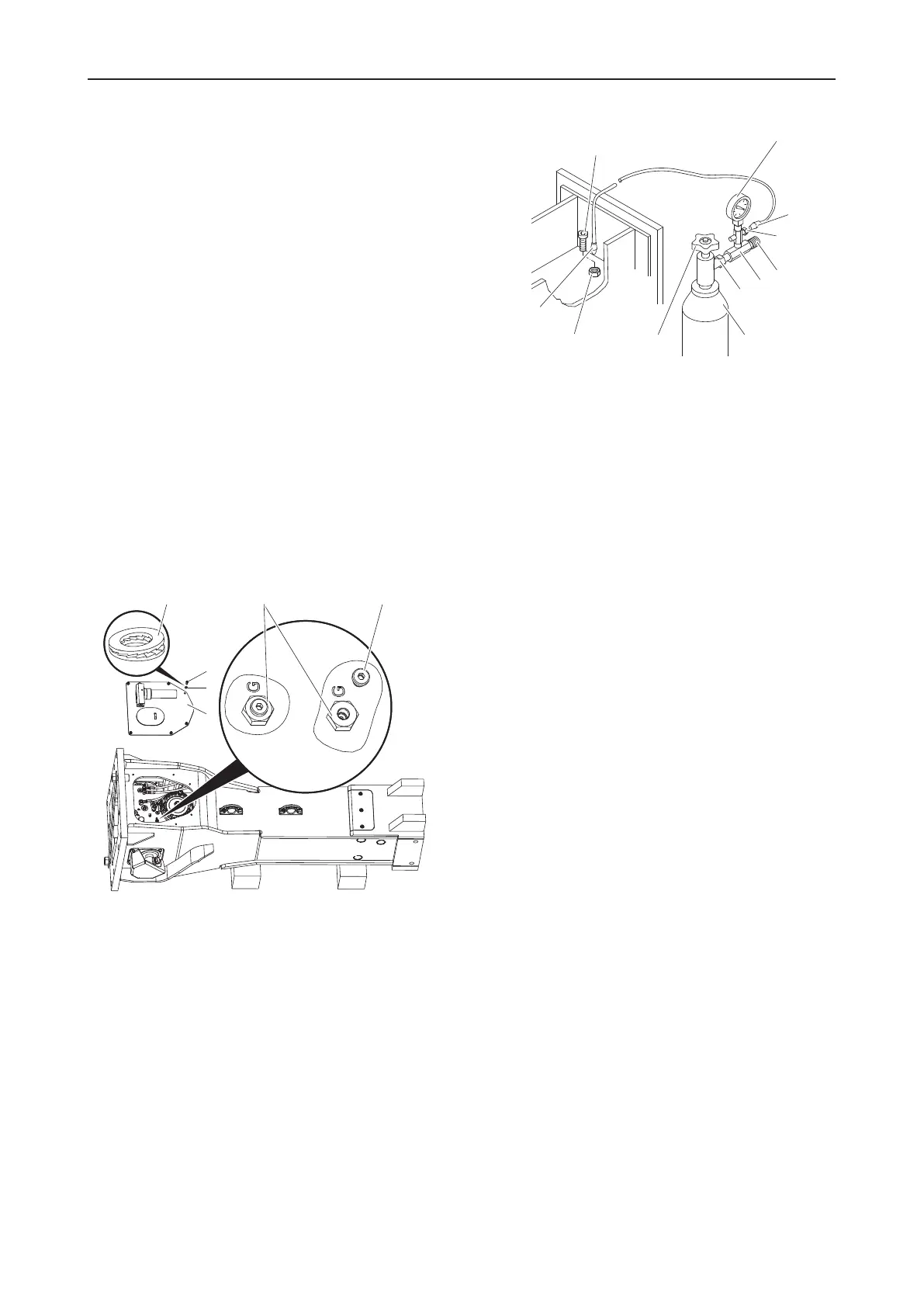
3.2.1 Filling procedure
The following accessories can be supplied:
• 1 filling valve with pressure gauge 0-100bar, part
number 3361329516
• 1 filling hose 700mm length, part number
3361329517
or
• 1 filling hose 4000mm length, part number
3360479259
• 1 test pressure gauge ¼", 0-25bar, test category
1.6, part number 3361329518
• 1 nitrogen cylinder 2l, part number 3363034504
or
• 1 nitrogen cylinder 5l, part number 3363034506
• 1 country-specific adapter, if required (see additional
document, document number 3390710601)
The piston accumulator must to be filled through the fill-
ing valve. The filling valve is marked with »G« on the
cylinder cover. When filling the piston accumulator,
please observe the table above and follow the instruc-
tions provided step by step.
When the plate respectively the plates have not yet been
removed:
n
Remove the Allen screws(N) and the pairs of lock
washers(O).
n
Remove the plate(P) respectively the plates(P) from
the breaker box.
If a country-specific adapter(I) is required, it must be in-
stalled between the nitrogen cylinder and the pressure
relief valve(H).
1.
Connect the pressure relief valve(H) to the nitrogen
cylinder(J).
2.
Close the check valve(F) on the pressure relief
valve(H).
3.
Connect the filling hose end(V) to the minimess con-
nection(L) of the pressure relief valve.
4.
Open the valve(K) of the nitrogen cylinder.
5.
Remove the threaded plug(T) from the filling
valve(G).
6.
Push the free filling hose end(V) onto the filling
valve(G).
7.
Slowly open the check valve(F) on the pressure re-
lief valve to let the nitrogen flow into the piston accu-
mulator.
8.
Read out the pressure increase from the pressure
gauge(U).
9.
Close the check valve(F) on the pressure relief valve
when the piston accumulator has reached the re-
quired prefill pressure +10%.
10.
Pull the filling hose out of the filling valve(G).
11.
Check the pressure in the piston accumulator and let
gas escape until the required gas pressure has been
reached.
12.
Install the threaded plug(T) in the filling valve(G)
and tighten it to the required tightening torque (see
chapter Bolt connections / Tightening torques).
13.
Close the nitrogen cylinder valve(K).
14.
Remove the label "Depressurised high pressure ac-
cumulator and piston accumulator" from the hydraulic
breaker's hose connection.
 Loading...