Safety and operating instructions
© Construction Tools GmbH | 3390 5149 01 | 2020-09-22
Original Instructions
17
LED 4
LED 5
LED 6
LEDs 4, 5 and 6 flash simultaneously
Insulation fault detected
If an insulation fault is detected, a restart
is automatically blocked. The Hydro
Magnet cannot be switched on again.
This is a safety risk! Lethal contact
voltages can occur on metal parts!
Contact a qualified electrician immedi-
ately.
LED 4
LED 5
LED 6
LEDs 4, 5 and 6 light up simultaneously
and 100% flashes
Pre-alarm over temperature of the con-
trol electronics
Although the generator system is de-
signed for continuous operation, it may
be too hot in some special cases. This
risk exists when at full load, if the cool-
ing of the generator and the control
electronics is disabled or if the tempera-
ture of the cooling air exceeds the maxi-
mum allowable value of 40°C (104°F).
Warning temperature of control electron-
ics
The temperature in the control electron-
ics, has exceeded the pre-alarm limit
value. The generator system is blocked
from restarting until the temperature has
decreased in the control electronics
again and overtemperature - advance
warning goes out. If the generator sys-
tem is still used despite an overtempera-
ture - advance warning under load, the
temperature will continue to rise, and af-
ter about 10 minutes an immediate shut-
down of the system will occur due to ex-
ceeded temperature limit.
LED 4
LED 5
LED 6
LEDs 4, 5 and 6 and 100% flash
Temperature exceeded control electron-
ics
The temperature in the control electron-
ics has exceeded the allowed limit, and
the system is switched off immediately
without warning. Lifted loads may be
dropped from the magnet plate. After
the automatic shutdown of the system, a
lock-prevention prohibits switching on
the magnet plate again as long as it
takes the temperature of the control
electronics to fall below the warning
temperature.
Note: Newer systems report a tempera-
ture overshoot as system failure (LED 5
flashes). In newer systems, the control
electronics will not shut off the magnets
for safety reasons. However, this mes-
sage MUST ALWAYS be considered the
most critical operating point!
3.2 Function
The operation of a Hydro Magnet is described in a
greatly simplified version below:
The pressure line »P« supplies oil at the operating pres-
sure of the carrier to the generator of the Hydro Magnet.
The tank line »T« returns the oil to the tank of the carrier.
The generator generates the energy for the Hydro Mag-
net. The control electronics are attached to the genera-
tor. This is connected with the display.
The Hydro Magnet is operated by a manual or foot con-
trol in the driver's cab of the carrier. The operating condi-
tions of the system are controlled on the display.
Lift load (switch-on magnet plate)
After switching on, the generator outputs a voltage for
magnetizing the magnet plate. When you first switch on
after the start of the system, the current flowing in the
magnet plate increases relatively slowly until the rated
current is reached. The nominal voltage at the magnet
plate is then about 230V.
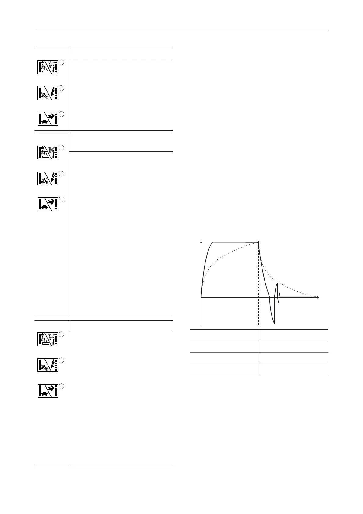
This process is illustrated in the following drawing as a
dashed curve.
1 Magnetization
2 Demagnetization
x Time
y Magnetic tractive force
In this graph it can be seen that it takes a relatively long
time for the magnet plate to reach its maximum magnetic
tractive force to lift a load. To speed up this relatively
slow magnetization, the Hydro Magnet uses a quick im-
pulse excitation method for all the following magnetiza-
tion processes. The quick magnetization with impulse
excitation is shown in the figure as a black curve.
Drop load (switch-off magnet plate)
 Loading...