7
3. INSTALLATION
3.1. Mounting dimensions
3.1.1. Model Compact (EE771-A and EE771-B)
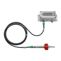
3.1.2. Model remote sensing probe (EE771-C)
115 (4.53)
145 (5.71)
129 (5.08)
60 (2.36)
60 (2.36)
56 (2.2)
40 (1.57)
207
cable gland
M16x1.5
cable gland
M16x1.5
Cross-section
bore hole:
Drilling Plan:
The bottom part of the housing is mounted with
4 screws (not in the scope of supply)
Max. screw diameter: 4.5 mm (0.17 inch).
e.g. 4.2 x 38 mm DIN 7938H Screws
Measurement ball valve
Dimensions in mm (inch)
183 (7.2)
173 (6.81)
Measurment ball valve Thread A B
DN15 R
p
1/2" 100±8 (3.94±0.32) 92 (3.62)
DN20 R
p
or NPT 3/4” 72 (2.83) 92 (3.62)
DN25 R
p
or NPT 1” 83 (3.27) 124 (4.88)
DN32 R
p
1 1/4" 100 (3.94) 124 (4.88)
DN40 R
p
or NPT 1 1/2" 110 (4.33) 147 (5.79)
DN50 R
p
or NPT 2” 131 (5.16) 147 (5.79)
dimensions in mm (inch)
Female thread: BSP thread acc. EN 10226 (old DIN 2999) or NPT
A A B
Only at DN15:
Reduction
3/4“-1/2“
173 (6.81)
 Loading...