M200 / M205 / M100 / M105 Series Revision A
Disassembly/Reassembly Detailed Disassembly/Reassembly Procedure for each Part/Unit 49
Confidential
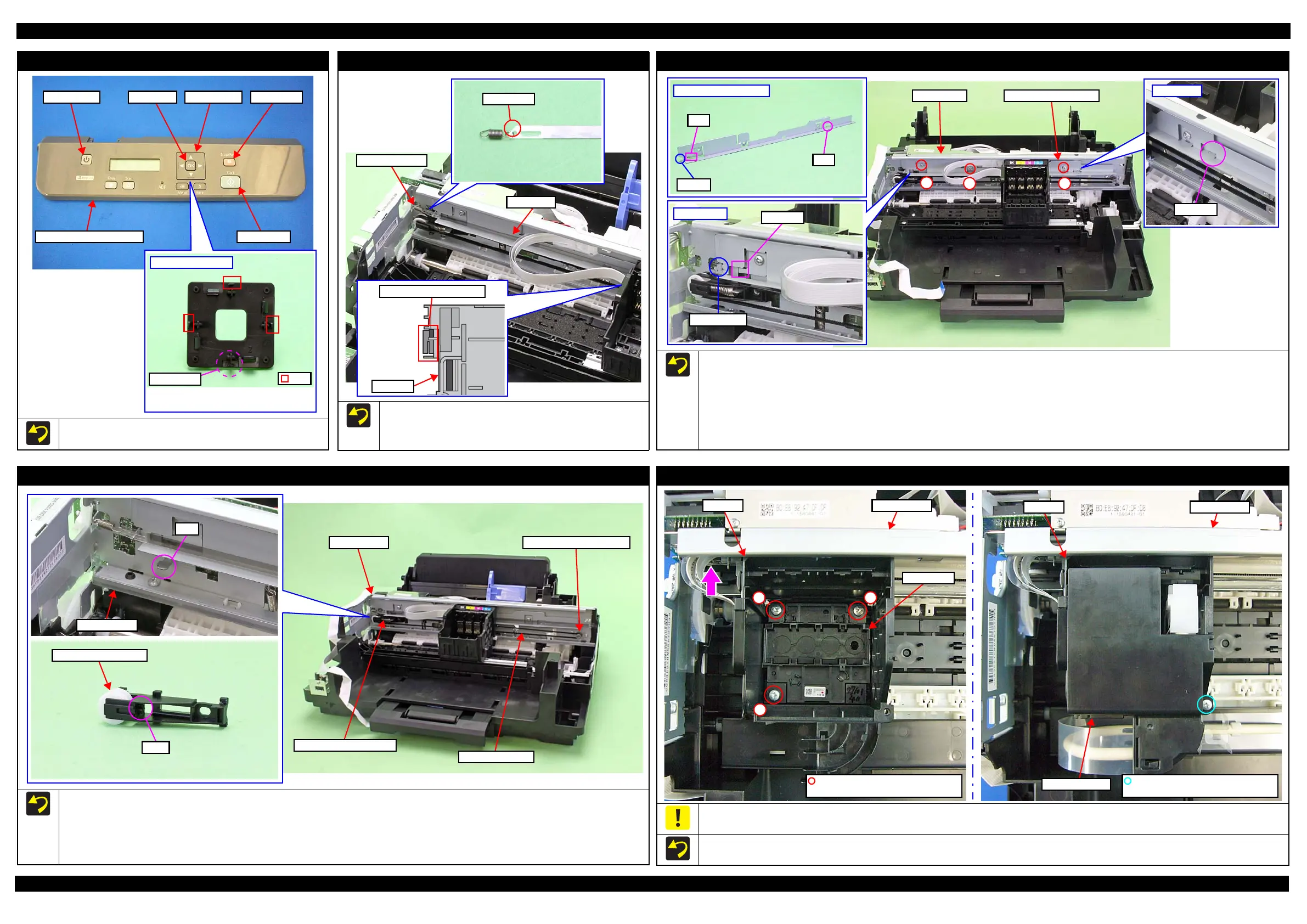
Panel Buttons (M200/M205 Series)
When attaching the Select Button to the Panel Housing Upper Assy,
attach the Select Button with its side without any rib downward.
Select Button (back)
Rib
No rib here.
Start button
Stop ButtonSelect ButtonOK ButtonPower Button
The side without any rib must be the side of
down arrow.
Panel Housing Upper Assy
CR Scale
Attach the CR Scale to the hook on the left of the Main Frame
with the black triangle mark upward.
Make sure to put the CR Scale through the slit of the CR
Encoder Sensor.
Cut Section
Slit of CR Encoder Sensor
CR Unit
CR Scale
Extension spring
CR Scale Cover Frame
When installing the CR Scale Cover Frame, install the CR Scale Cover Frame to the Main Frame following the standard below and tighten the screw
in the procedure below.
80-digit side
• Align the protrusions of the Main Frame with the cutout of the CR Scale Cover Frame.
• Insert the rib of the CR Scale Cover Frame to the hole of the Main Frame.
0-digit side
• Insert the rib of the CR Scale Cover Frame to the hole of the Main Frame.
CR Scale Cover Frame
Cutout
Rib
Rib
0-digit side
Inset rib.
80-digit side
Align cutout.
Inset rib.
Main Frame CR Scale Cover Frame
12
3
CR Driven Pulley Assy / CR Timing Belt
When installing the CR Driven Pulley Assy and CR Timing Belt, follow the procedure below.
1. Install the CR Driven Pulley Assy to the Main Frame.
2. Attach the Compression Spring 20.91 in the order from the dowel on the CR Driven Pulley Assy to the rib on the Main Frame.
3. Attach the CR Timing Belt to the CR Driven Pulley Assy.
4. Attach the CR Timing Belt on the pinion gear of the CR Motor while pushing the CR Driven Pulley Assy to the 0-digit side.
Main Frame
Rib
CR Driven Pulley Assy
Dowel
Main Frame
CR Timing Belt
Pinion gear of CR Motor
Compression Spring 20.91
Printhead / Adapter Cover
When removing/replacing the Printhead or the Adapter Cover, not to apply excessive downward force when tightening the screws. Otherwise, the
Main Frame may be deformed by applying force perpendicularly when tightening the screws and it may affect print quality.
Tighten the screws of the Printhead in the order indicated in the figure above while pressing the Printhead in the direction of the arrow.
12
3
Main Frame
Printhead
CR Unit
C.B.P-TITE SCREW 3x10 F/ZN-3C
(7 ± 1 kgf·cm)
CR Unit Main Frame
Adapter Cover
C.B.P-TITE SCREW 2.5x8 F/ZN-3C
(2.5 ± 0.5 kgf·cm)
 Loading...