M200 / M205 / M100 / M105 Series Revision A
Disassembly/Reassembly Routing FFCs/cables 58
Confidential
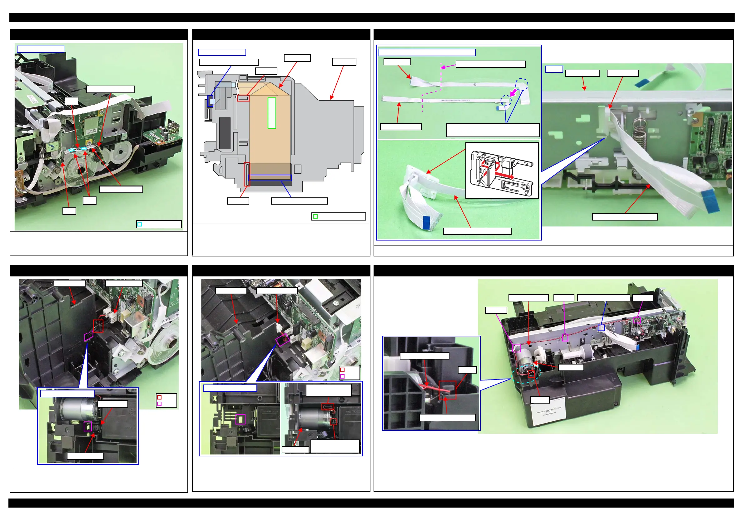
PF Encoder Sensor
Route the PF Encoder through ribs of the Main Frame and connect the
connector (CN7) of the Main Board. Then secure with the double-sided tape
(x2) on the position shown in above.
Left side of printer
PF Encoder Sensor
PF Encoder FFC
Rib
Double Side Tape
CN7
Ribs
Head FFC (Routing on the CR Unit)
Route the CR Encoder FFC along the Rib A and connect it to the
connector of the CR Encoder.
Route the Head FFC through the rib A and B, and then connect it to the
connector of the Printhead.
Double-sided tape
Connector of Printhead
Left side of CR Unit
Connector of CR Encoder
Rib A
Head FFC
CR Unit
Rib B
Head FFC (Routing on the Main Frame)
Align the Head FFC and CR Encoder FFC, and then route them through the FFC Holder as shown in the figure above.
Aligning Head FFC with CR Encoder FFC
Head FFC
CR Encoder FFC
Fold here inside FFC Holder
Stack the Head FFC over the CR Encoder
FFC to keep the Head FFC on top.
Head FFC/CR Encoder FFC
FFC Holder
Rear
FFC HolderMain Frame
Head FFC/CR Encoder FFC
PS Unit
Pull out the PS Unit cable from the hole of the Frame Base first, and then
route it through the rib of the Frame Base.
Put the ferrite core into the position shown in the figure above.
Bottom of Frame Base
PS Unit cable
Ferrite core
PS Unit cableFrame Base
Hole
Rib
PF Motor
Route the PF Motor cable as follows.
1. Pull out the PF Motor cable from the hole of the Frame Base.
2. Install the PF Motor, and secure the PF Motor cable (black) with the rib of
the Frame Base, and then route it through the rib of the Frame Base.
Bottom of Frame Base
PF Motor
Route PF Motor
cable through rib.
Secure PF Motor
cable (black) with rib.
PF Motor cable
Hole
Rib
Frame Base
CR Motor
Route the CR Motor cable as follows before installing the Shield Plate.
1. Route the CR Motor cable (black) around the rib A of the Frame Base (two turns).
2. Route the CR Motor cable (red) through the rib B of the Frame Base, and then route it through the rib A taking care not to let the CR Motor cable (red)
come over the CR Motor cable (black).
3. Twist the CR Motor cable (black) and CR Motor cable (red) twice, and then route them through the hook C of the Main Frame.
4. Route the CR Motor cable (black) and CR Motor cable (red) in the order of hook D of the Main Frame, groove of the FFC Holder, and hook E of the Main
Frame.
CR Motor cable (red)
Rib A
CR Motor cable (black)
Hook C
Rib B
CR Motor
Hook EGroove of FFC HolderCR Motor cable Hook D
 Loading...