Epson Artisan 800/Epson Stylus Photo PX800FW/TX800FW/Epson Artisan 700/Epson Stylus Photo PX700W/TX700W
Disassembly Procedures
https://www.manualsbooks.com
4.2.3.2
Main Board / Grounding Plate M/B
Parts/Components need to be removed in advance:
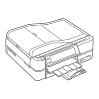
ADF Unit (Artisan 800/PX800FW/TX800FW only)/Scanner Unit/Upper Left
Housing/Paper Guide Top Assy/Upper Housing/Hinge/Rear Right FAX Housing/
Right Housing
Removal procedure
1.
Disconnect all the cables and FFCs from the connectors on the Main Board.
Table 4-4. Connectors on the Main Board
Artisan 800/
PX800FW/
TX800FW
Artisan 700/
PX700W/
TX700W
Table 4-4. Connectors on the Main Board
Figure 4-39. Connector position on the Main Board
When printing the CDR, the CDR Tray feed amount is adjusted
with compensation considering the deterioration of the CDR Tray,
and the correction level is determined by the number of printed
CDRs. If the data on the EEPROM can not be copied when
replacing the Main Board, banding may occur while printing CDR
due to improper corrections caused because the data of the number
of printed CDRs can not be transferred.
When this happens, replace the CDR Tray Assy with a new one
together with the Main Board. (See
Artisan 800/
PX800FW/
TX800FW
Artisan 700/
PX700W/
TX700W
Scanner Cover Open Sensor FFC
Decompression Pump Motor Cable
The disassembly/reassembly procedures of Artisan 700/PX700W/
TX700W differ from those of Artisan 800/PX800FW/TX800FW.
See 4.3.2.2 "Main Board/Grounding Plate M/B (Artisan 700/
PX700W/TX700W)" (p196) for the procedures.
 Loading...