Epson Artisan 810/835/837/710/725/730/Epson Stylus Photo PX810FW/TX810FW/PX820FWD/TX820FWD/PX830FWD/PX710W/TX710W/PX720WD/TX720WD/PX730WD/TX730WD
Revision G
DISASSEMBLY/ASSEMBLY Disassembly/reassembly procedures specific to Artisan 710/PX710W/TX710W 190
Confidential
DISASSEMBLING THE PANEL UNIT
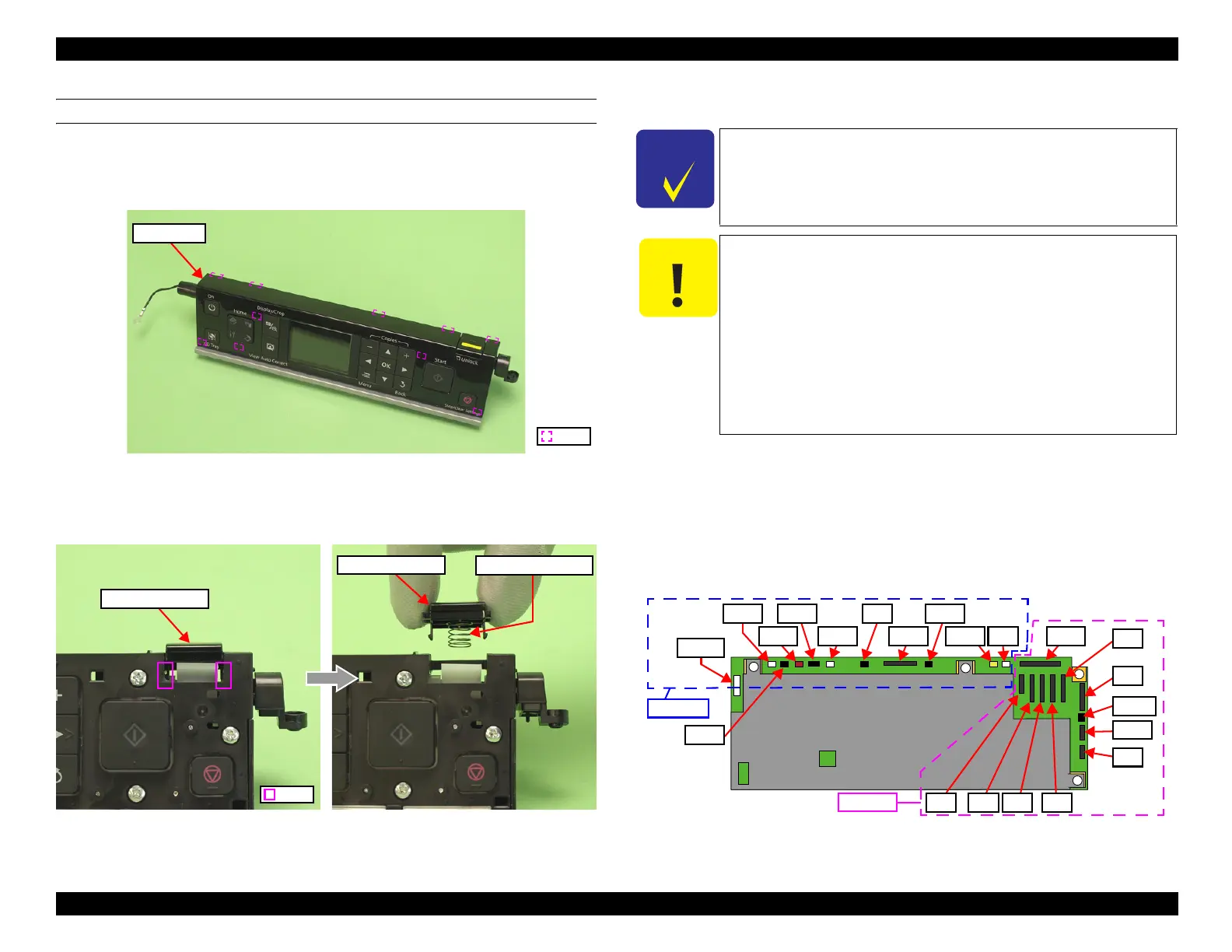
Removal procedure
1. Release the hooks (x10) that secure the Panel Cover, and remove the Panel
Cover from the Panel Unit.
Figure 4-181. Disassembling the Panel Unit (1)
2. Release the hooks (x2), and remove the Panel Lock Button and the Lock
Release Spring.
Figure 4-182. Disassembling the Panel Unit (2)
4.3.2.2 Main Board/Grounding Plate M/B
Parts/Components need to be removed in advance:
Scanner Unit/Upper Left Housing/Paper Guide Top Assy/Upper Housing/Hinge/
Rear Right Housing/Right Housing
Removal procedure
1. Disconnect all the cables and FFCs connected to the section A on the Main
Board. (See
"Connectors on the Main Board" (p. 126).)
Figure 4-183. Connector positions on the Main Board
Panel Lock Button
Lock Release Spring
The disassembly/reassembly procedures for Artisan 810/835/837/
PX810FW/TX810FW/PX820FWD/TX820FWD/PX830FWD differ
from those for Artisan 710/725/730/PX710W/TX710W/PX720WD/
TX720WD/PX730WD/TX730WD, see
"4.2.4.2 Main Board /
Grounding Plate M/B" (p.126) for the procedures.
When printing the CDR, the CDR Tray feed amount is adjusted
with compensation depending on the deterioration of the CDR
Tray, and the correction level is determined by the number of
printed CDRs. If the data on the EEPROM can not be copied when
replacing the Main Board, banding may occur while printing CDR
due to improper corrections caused because the data of the number
of printed CDRs can not be transferred.
When this happens, replace the CDR Tray Assy with a new one
together with the Main Board. (See
"4.2.5.9 CDR Tray Assy"
(p.153).)
CN22
CN24 CN41
CN10
CN12 CN9 CN33
CN6 CN4 CN3 CN2
CN1
CN5
CN31
CN7
CN13
CN21
CN501
Section B
Section A
CN49 CN8
Note * : Artisan 730/PX730WD/TX730WD only
CN19*
 Loading...


