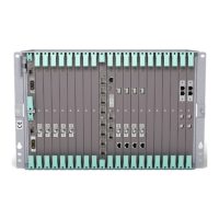
Replacing an NPU1 C with an NPU1 D
Note: If you do not remove the NPU1 C within 90 seconds, the NPU
automatically performs a cold restart and the unit is taken into
service in about 180 seconds. The amount of time may vary
depending on the circumstances.
When the unit performs a cold restart, several traffic types are
interrupted as described in Section 4.3 on page 7.
7. Remove the RMM from the NPU.
ERICSSON
N
P
U
1
C
TR2/LAN
TR5
OUT TR5 IN
OUT TR4 IN
O&
M
TR:3A-3D
TR:2A-2
D
User I/O:1A-1I
F
P
BR
NPU1 C
11981
RMM
RYS 110 243/1 P1A
BS80000001
20051101
Barcode 128
INSERT
4.3.1.2 Removing an NPU1 C from the Secondary Slot
Remove an NPU1 C from the secondary slot by performing the following steps:
1. Clean any switch ports connected to the NPU1 C by assuring that the
following conditions are met:
• The port is not a member of any VLAN. See Configuring an Ethernet
Layer 2 Connection, Reference [17].
• The port is not a member of any LAG. See Configuring Link Aggregation
Groups (LAG), Reference [18].
• The port has no bandwidth policing. See Configuring Quality of Service,
Reference [19].
• The port has no RSTP or MSTP enabled. See Configuring Spanning
Tree, Reference [20].
• The port has no MAC white list connected. See Configuring Ethernet
Security and Admission Control, Reference [21].
• The port is not member of any mirror connection. See Performance
Management Operations, Reference [22].
If these connections are still present, clearing the position in Step 9 results
in an error.
10
107/1543-HRA 901 20-V11 Uen B | 2015-12-01
 Loading...
