Replacing an NPU1 C with an NPU1 D
10. On the File menu, click Save.
11. In the Management Tree, right-click the NE.
12. Point to View Status and click Alarms, and make sure that the
icon is
not shown.
4.3.2 Adding an NPU1 D
Caution!
Electrostatic Discharge (ESD) may damage the equipment. Always use an
approved ESD wrist strap to avoid damage to components fitted on printed
circuit boards.
Note: When replacing two NPU1 C units configured for Ethernet Switch
Protection, both units must be removed and both positions cleared
before inserting a new NPU1 D.
To minimize downtime when adding two NPU1 D units, insert and configure an
NPU1 D in the primary slot, before inserting an NPU1 D into the secondary slot.
4.3.2.1 Adding an NPU1 D to the Primary Slot
To add an NPU1 D to the primary slot, and move the licenses from the NPU1 C
to the NPU1 D by reusing the RMM from the NPU1 C:
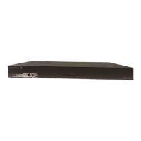
1. Remove the NPU1 D from the ESD-protective packaging.
2. Insert the RMM from the NPU1 C into the RMM holder on the NPU1 D.
ERICSSON
N
P
U
1
D
SYNC
2 MHz
TR:3
TR:2
TR:5/LAN
10/100/1000 BASE-T
SYNC
1PPS + ToD
TR:6
10/100/1000 BASE-T
O&
M
F
P
BR
User I/O
NPU1 D
TR:4
1G/10G BASE-T/X
1G/10G BASE-T/X
1000 BASE-T/X
17189
RMM
RYS 110 243/1 P1A
BS80000001
20051101
Barcode 128
INSERT
12 107/1543-HRA 901 20-V11 Uen B | 2015-12-01