- 7 -
V. Disassembly
In case of trouble, etc., necessitating dismantling, please dismantle in the order shown in the illustrations. Reassemble
in the reverse order.
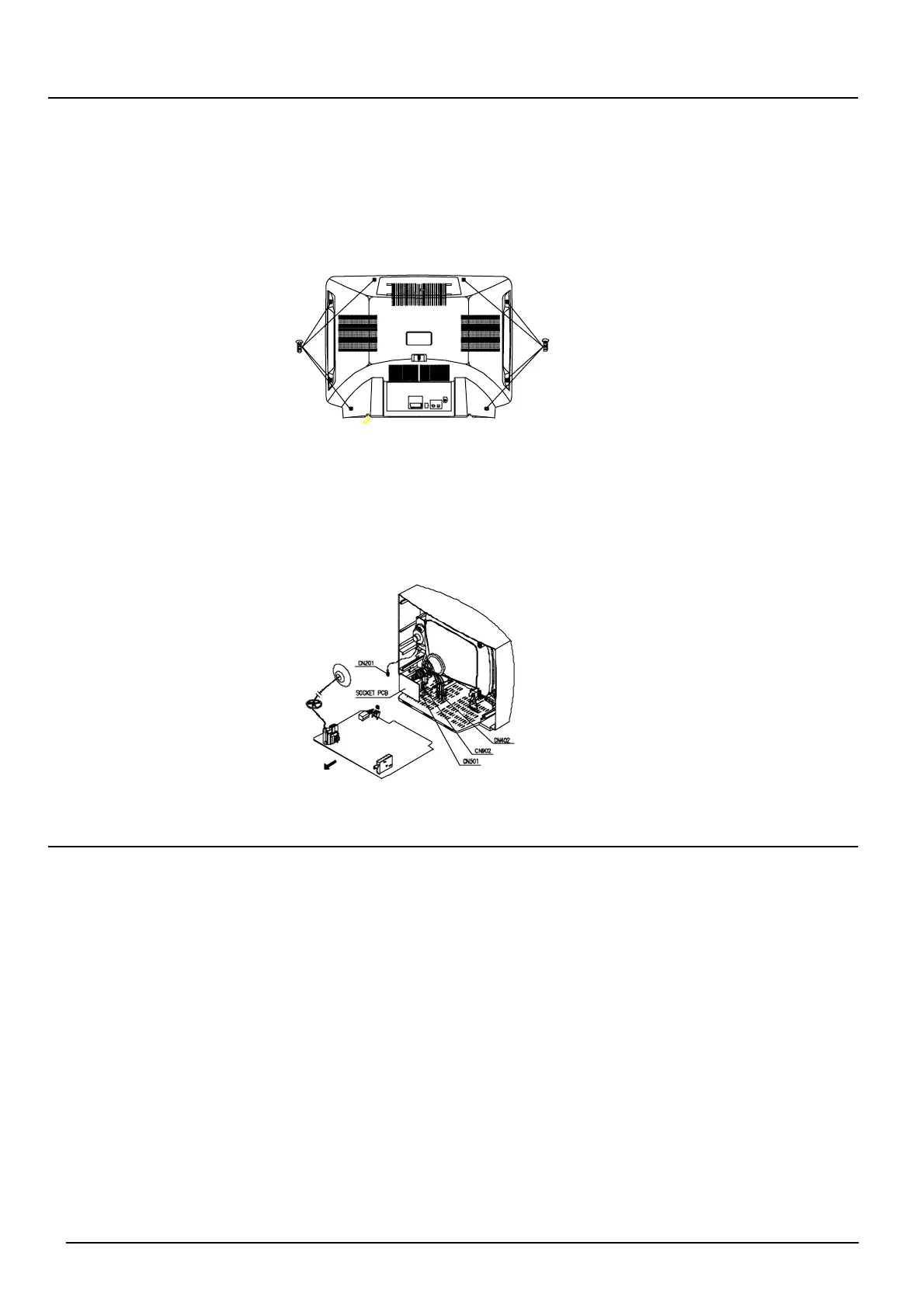
i. Removal of the Back Cover
1 Remove the screws as shown.
2 Pull out the back cover slightly.
3 Pull up the connector of the two lead wires (red black) connecting to the speakers on
the cover from the MAIN PCB.
ii. Removal of the Main PCB
1 Remove the two screws.
2 Slide out the TV chassis slightly; pull up the connector of AC cord from PCB; Pull up the CRT PCB from CRT.
3 Remove the anode cap from the picture tube. To avoid a shock hazard, be sure to discharge the picture tube's
anode to the chassis ground before removal.
4 Take out the TV chassis.
VI. Alignment Instructions
i. Before Adjustment and Maintenance
A. Don't short any two soldering points or connect any component while TV set is power on.
B. Pull out power plug before maintenance.
C. In order to ensure safety all components replaced should be identical with originals.
(For further details, refer to the component name and component No. in PARTS LIST.)
D. Must warm up for 30 minutes or more and degauss CRT thoroughly with demagnetiser before alignment.
ii. Equipments for adjustment
A. Pattern generator B. Digital voltmeter
C. High voltage meter D. Sine wave signal generator
E. Demagnetiser F. Personal computer (486)
G. DC regulated power supply H. Oscilloscope
I. CRT colour analyzer (MINOLTA CA-100)
iii. Input signals
A. PHILIPS pattern B. Color bar
C. Cross hatch D. Grey scale bar
E. Monoscope pattern F. Moving picture with sound