Do you have a question about the ero electronic PKP and is the answer not in the manual?
Main title indicating the document's purpose.
Instructions for permanent installation in an electrical panel, including cutout dimensions and gasket use.
Diagram showing the rear terminal block connections for the instrument.
Wiring diagram for thermocouple input, including notes on cable shielding and grounding.
Wiring diagram for RTD input, emphasizing line resistance and grounding.
Wiring diagrams for mA, mV, and V inputs, with notes on line resistance and impedance.
Wiring diagrams for 2, 3, and 4-wire transmitter inputs.
Diagram illustrating the wiring for a 3-wire transmitter input.
Diagram illustrating the wiring for a 4-wire transmitter input.
Wiring diagram for auxiliary inputs, detailing connection to measuring input and power supply.
Wiring diagram for logic inputs DIG 1, 2, 3, specifying connections and impedance.
Wiring diagrams for logic inputs 1 through 4, with notes on cable and contact type.
Wiring diagrams for logic inputs 5 through 8, with notes on cable and contact type.
Wiring diagram for current transformer input, used for measuring load current and output failure detection.
Wiring diagrams for relay outputs 1 through 4, detailing contact rating and warnings.
Wiring diagrams for relay outputs 10 through 14, specifying contact rating.
Wiring diagrams for relay outputs 15 through 19, detailing contact rating and general notes.
Wiring diagram for voltage outputs used for SSR drive, specifying logic levels and current limits.
Wiring diagram for TRIAC outputs, detailing switching mode, rated current, voltage, and notes.
Wiring diagram for servomotor output, including notes on interlocking and contact rating.
Wiring diagram for analog output 5, showing 20mA connection and load limits.
Wiring diagram for analog output 6, showing 20mA connection and load limits.
Wiring diagram for the RS-485 serial interface, including notes on cable length and signal sense.
Diagram for power line connections, including voltage, current, safety requirements, and notes.
Step-by-step instructions on how to safely remove the instrument from its enclosure using locking mechanisms.
Guide for setting the J103 DIP switch to select the desired main input type and range.
Guide for setting the J102 DIP switch to select the desired auxiliary input type.
Instructions for configuring outputs 3 and 4 as independent relays or a servomotor output using J204 and J205.
Explanation of how to select between Current Transformer (CT) input or Feedback input.
Instructions for setting the V301 DIP switches to select the desired input type.
Guidance on verifying installed options like auxiliary input and digital inputs using integrated circuits KY101 and KY103.
How to select operative modes (run time, configuration, security code) using the V101 switch.
General notes on parameter security, families, groups, and the use of security codes for modification.
Procedure for setting the security code mode and viewing firmware version.
How to set the 'S.run' parameter for run time security, with options for no protection, full protection, or code entry.
How to set the 'S.CnF' parameter for configuration security, with options for protection levels and codes.
How to protect or not protect run time group 2 using the run time security code.
Overview of hardware selection for starting configuration or run time modes, including controller and programmer modes.
Explanation of special symbols used in mnemonic code visualization and their corresponding characters.
Explanation of the function of each button (MENU, FUNC, MAN) and arrow keys for parameter modification and manual mode.
Procedure to enter and navigate the configuration mode, including accessing Configuration Group 1.
How to monitor configuration parameters without modifying them, while the instrument operates in run time mode.
How to start the modify mode, including stopping control outputs and disabling serial links.
Steps to start the modify mode, load default configuration, and access parameters.
Introduction to configuration parameters, noting that only specific ones are shown based on hardware and configuration.
How to configure main and auxiliary input settings, including line frequency and input types.
Parameter [C.d01] for setting the line frequency.
Parameter [C.d02] for selecting the main input type and its corresponding range.
Parameter [C.d03] for setting the decimal point position for input values.
Parameter [C.d04] to enable or disable square root extraction for main input.
Parameter [C.d05] to set the initial scale read-out for the main input.
Parameter [C.d09] to define the function of the auxiliary input, such as not used or bias.
Parameter [C.d10] to select the type of the auxiliary input, e.g., 0-20 mA or 1-5 V.
Parameter [C.d07] to set the offset value for the main input.
Parameter [C.d08] to apply a digital filter to the displayed main input value.
Parameter [C.d09] to define the function of the auxiliary input, such as not used or bias.
Parameter [C.d10] to select the type of the auxiliary input, e.g., 0-20 mA or 1-5 V.
Parameters [C.d11] and [C.d12] for setting the initial and full scale read-out of the auxiliary input.
Parameter [C.d13] to apply a digital filter to the measured auxiliary input value.
Notes on exiting configuration group 1 and verifying programmed span for linear input.
Parameter [C.F01] to enable or disable the split range feature for controlling two actuators simultaneously.
Parameter [C.E01] to define the function of OUT 1, such as control, alarm, or event output.
Parameter [C.E02] to define the function of OUT 2, such as control, alarm, or event output.
Parameter [C.E03] to define the function of OUT 3, including servomotor drive options.
Parameter [C.E04] to define the function of OUT 4, including servomotor drive options.
Parameter [C.E05] to select the servomotor type (close loop, open loop with valve indication) if configured.
Parameter [C.E06] to display valve position for open loop servomotor drive output.
Parameters [C.E07] and [C.E08] to define the function and range for analog output 5.
Parameters [C.E09] and [C.E10] for setting the initial and full scale values for analog output 5 retransmission.
Parameters [C.E12] and [C.E13] to define the function and range for analog output 6.
Parameters [C.E14] and [C.E15] for setting the initial and full scale values for analog output 6 retransmission.
Notes on exiting configuration group 2 and verifying parameter congruence.
Parameter [C.F01] to enable or disable the split range feature for controlling two actuators simultaneously.
Parameter [C.F06] to condition the main control output (PID, QUICK OPENING, EQUAL PERCENTAGE).
Parameters [C.F02] and [C.F03] for setting gain and bias for the main control output when split range is enabled.
Parameters [C.F07] and [C.F08] for scaling the main output to engineering units and setting decimal point.
Parameter [C.F09] to set the initial scale readout for the main control output.
Parameter [C.F10] to set the full scale readout for the main control output.
Parameters [C.F04] and [C.F05] for setting gain and bias for the secondary control output when split range is enabled.
Parameter [C.F12] to condition the secondary control output (PID, QUICK OPENING, EQUAL PERCENTAGE).
Parameters [C.F13] and [C.F14] for scaling the secondary output to engineering units and setting decimal point.
Parameter [C.F15] to set the initial scale readout for the secondary control output.
Parameter [C.F16] to set the full scale readout for the secondary control output.
Parameter [C.F17] for auxiliary conditioning of the secondary output.
Notes on exiting configuration group 3 and verifying split range parameter.
Parameter [C.G01] to enable or disable the SMART function for automatic control optimization.
Parameter [C.G02] to select the control action type (PID or PI).
Parameter [C.G03] to enable or disable the manual function.
Parameter [C.G04] to set the value for AUTO to MANUAL transfer, including bumpless options.
Parameter [C.G05] to select the transfer type (bumpless or bumpless balanceless) from MANUAL to AUTO.
General notes on how the instrument restarts after a power down using St.Pr and St.Fn parameters.
Parameter [C.G06] to define the startup behavior when the device operates as a controller.
Notes on auto/manual control mode selection via logic input and instrument behavior.
Parameter [C.G07] for configuring program restart behavior after a power failure.
Parameter [C.G08] to set the tracking band for program restart.
Parameter [C.G09] to define output safety conditions based on input status.
Parameter [C.G10] to set the safety value for output when specific conditions are met.
Parameter [C.H01] to define the function of digital input DIG 1, such as program selection or RUN/HOLD.
Parameter [C.H03] to define the function of digital input DIG 2.
Parameter [C.H05] to define the function of digital input DIG 3.
Parameter [C.H04] to set the contact status (closed or open) for digital input DIG 2.
Parameter [C.H06] to set the contact status (closed or open) for digital input DIG 3.
Parameter [C.H07] to define the function of logic input IN 1, such as program selection or RUN/HOLD.
Parameter [C.H11] to set the time duration for the "End of cycle" annunciator.
Parameter [C.H12] to set the time duration for the "End of profile" annunciator.
Notes on ensuring consistency of digital input functions and avoiding duplicate assignments.
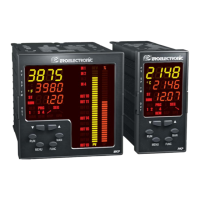
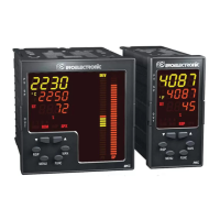
Parameter [C.I01] for MKP models, to select whether the green bargraph shows process variable or deviation.
Parameter [C.I02] for MKP models, to select whether the orange bargraph shows operative set point or process output.
Parameter [C.I03] for MKP models, to set the initial scale value for the bargraph.
Parameter [C.I04] for MKP models, to set the full scale value for the bargraph.
Parameter [C.I05] for MKP models, to set the resolution of the deviation bargraph.
Parameter [C.I06] to align the operative set point at startup, with notes on error conditions and program execution.
Parameter [C.I07] to select how the set point is displayed during controller operation when performing a set point ramp.
Parameter [C.I08] defining servomotor behavior when output limits are reached.
Parameter [C.I09] to set a threshold for enabling the soft start function.
Parameter [C.I10] to select the time out duration for various functions.
Parameter [C.I11] to configure the output failure detection function for time proportional outputs.
Parameter [C.I12] to set the primary current value of the current transformer for OFD.
Parameter C.I13 to assign the OFD alarm to a specific output or display.
Parameter [r.F01] to define the type of alarm for OUT 1 (process, band, deviation, main/secondary output).
Parameter [r.F02] to configure alarm 1 behavior (automatic/manual reset, acknowledgment).
Parameter [r.F03] to set the action (direct or reverse) for alarm 1.
Parameter [r.F04] to enable or disable the stand-by (mask) function for alarm 1.
Parameter [r.F05] to define the type of alarm for OUT 2.
Parameter [r.F06] to configure alarm 2 behavior (automatic/manual reset, acknowledgment).
Parameter [r.F07] to set the action (direct or reverse) for alarm 2.
Parameter [r.F08] to enable or disable the stand-by (mask) function for alarm 2.
Parameter [r.F09] to define the type of alarm for OUT 3.
Parameter [r.F10] to configure alarm 3 behavior (automatic/manual reset, acknowledgment).
Parameter [r.F11] to set the action (direct or reverse) for alarm 3.
Parameter [r.F12] to enable or disable the stand-by (mask) function for alarm 3.
Parameter [r.F13] to define the type of alarm for OUT 4.
Parameter [r.F14] to configure alarm 4 behavior (automatic/manual reset, acknowledgment).
Parameter [r.F15] to set the action (direct or reverse) for alarm 4.
Parameter [r.F16] to enable or disable the stand-by (mask) function for alarm 4.
Parameter [r.F17] to configure the OFD alarm (automatic/manual reset, acknowledge).
Parameter [r.F18] to set the action (direct or reverse) for the OFD alarm.
Parameter [r.F19] to load default data for configuration group 6.
Parameter [r.G01] to select the serial interface protocol (MODBUS, JBUS).
Parameter [r.G02] to set the device address for the serial link.
Parameter [r.G03] to set the baud rate for the serial link.
Parameter [r.G04] to configure the byte format (bits, parity) for the serial link.
Parameter [r.G05] to load default data for configuration group 7.
Parameter [r.H01] to enable or disable the feedback potentiometer calibration procedure.
Parameter [r.H02] to set the low limit position for the servomotor valve.
Parameter [r.H03] to calibrate the feedback low limit.
Parameter [r.H04] to set the high limit position for the servomotor valve.
Parameter [r.H05] to calibrate the feedback high limit.
Information on calibration completion, value checking, and potential repetition of the procedure.
Parameter [r.H6] to load default data for configuration group 8.
Parameter [r.I01] to set the tracking value added to the set point for upper limit tracking.
Parameter [r.I02] to set the tracking value subtracted from the set point for lower limit tracking.
Parameter [r.I03] to load default data for configuration group 9.
Parameter [r.L01] to load default values for all run time parameters, except for group 8.
Parameter [r.M01] to set the minimum proportional band for SMART algorithm.
Parameter [r.M02] to set the maximum proportional band for SMART algorithm.
Parameter [r.M03] to set the minimum integral time for SMART algorithm.
Parameter [r.M04] to set the maximum integral time for SMART algorithm.
Parameter [r.M05] to calculate the relative gain of the secondary output using SMART algorithm.
Parameter [r.M06] to load default data for the hidden group Hd.
Explanation of possible states in programmer mode: STAND-BY, EDIT, MANUAL, RUN, WAIT, HOLD, FAST, JUMP.
How to select and modify programs and segments in EDIT mode.
How to set control outputs or valve position manually in MANUAL mode.
How the instrument operates as a programmer in RUN mode, including visualization of data.
Explanation of the WAIT function, which stops program execution when measured value is outside tracking band.
How to temporarily stop program execution using HOLD mode, and its operative behavior.
How to quickly move forward or backward through program segments in HOLD mode.
How to jump forward or backward to segment beginnings or ends in HOLD mode.
Description of the right bargraph's function, showing operative set point or power output.
Description of the left bargraph's function, showing process variable or deviation error.
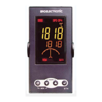
Explanation of the meaning of various indicators (°C, °F, ST, RUN, HLD, PRG, %, SEG) during run mode.
Explanation of indicators (°C, °F, ST, %, MAN, REM, RSP, SPX) and output status indicators (1, 2, 3, 4) during controller mode.
How to access and modify the set point directly when in controller or stand-by mode.
Procedure to enable the SMART function for automatic control optimization, including notes on ON/OFF control and safety key protection.
How to disable process control, operating the instrument as an indicator, and its effects on various functions.
How the clock calendar option enables automatic program starts, including setting time, day, and start conditions.
How the device measures and displays load current and leakage current for failure detection.
How to connect the device to a host computer via serial link, including LOCAL/REMOTE modes and necessary configuration.
How to perform a lamp test to verify display efficiency by activating all LEDs.
How to activate MANUAL mode manually or automatically, and how to access it.
How the instrument operates and displays values in MANUAL mode, including servomotor behavior.
Notes on bumpless transfer behavior between AUTO and MANUAL modes.
Procedure to set the instrument to controller mode from STAND-BY, including parameter selections and LED indications.
How the instrument operates as a controller, detailing standard features and availability of SMART function.
Explanation of the SMART function for automatic control optimization and its enabling/disabling procedure.
How to disable process control, operating the instrument as an indicator, and its effects on various functions.
How the clock calendar option enables automatic program starts, including setting time, day, and start conditions.
Notes regarding program selection by logic inputs and RUN/HOLD selection behavior.
General information on creating, modifying, and deleting simple programs, including segment limits.
How to access and use the EDIT mode for program creation, modification, or deletion.
Steps to modify an existing segment within a program.
Procedure for adding a segment to the end of or within an existing simple program.
Steps to delete a segment at the end of or within a program.
Procedure to delete a simple program, with notes on linked programs.
How to verify program parameters and control parameters after creation, including error detection.
Steps to create a linked program by combining simple programs, including repetitions.
Parameters for segment duration, gradient, PID group, and tracking group selection for Program 1.
Parameter [r.A11] to set the status (ON/OFF) of break events for segment 1.
Parameter [r.A12] to set the number of repetitions for a program.
Parameter [r.A13] to manage break event status at the end of program 1.
Parameter [r.A14] to define the control type (manual, set point, OPO) at the end of program 1.
Parameter [r.A15] to set the control output value at the end of program 1.
Parameter [r.A16] to set the set point value at the end of program 1.
Parameter [r.A17] to select the PID group to be used at the end of program 1.
Parameter [r.A18] to configure the first step of timer event 1 for program 1.
How to verify program parameters and control parameters after creation, including error detection.
Steps to create a linked program by combining simple programs, including repetitions.
Steps to modify an existing segment within a program.
Procedure for adding a segment to the end of or within an existing simple program.
Steps to delete a segment at the end of or within a program.
Procedure to delete a simple program, with notes on linked programs.
How to verify program parameters and control parameters after creation, including error detection.
Steps to create a linked program by combining simple programs, including repetitions.
Coding scheme for selecting model (PKP/MKP) and input types.
Coding scheme for configuring various output types (relay, TRIAC, SSR, mA).
Coding scheme for selecting available options like auxiliary power, RS485, clock calendar, and digital I/O.
Coding scheme for selecting the power supply type (AC or DC).
| Brand | ero electronic |
|---|---|
| Model | PKP |
| Category | Controller |
| Language | English |