36
10. Appendix
Use the following PIN diagrams, when directed by the respective
troubleshooting instructions.
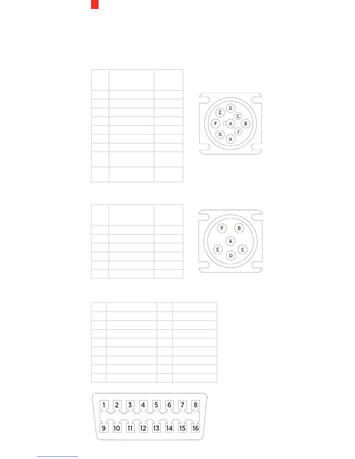
9-Pin J-BUS Connector and Diagram
PIN Description Wire
Color
(Typical)
A Ground (Earth) Black
B 12V Power Supply Red
C J1939 + (Data +) Yellow
D J1939 - (Data -) Brown
E J1939 Shield White
F J1708/J1587 + Green
G J1708/J1587 - Blue
H Not connected/
CAN2 High
J Not connected/
CAN2 Low
6-Pin J-BUS Connector and Diagram
PIN Description Wire
Color
(Typical)
A J1587 + (Data +) Green
B J1587 - (Data -) Blue
C 12V Power Supply Red
D Not Connected
E Ground (Earth) Black
F Not Connected
OBD-II Connector and Pin-out Diagram
PIN Description PIN Description
1 Vendor Option 9 Vendor Option
2 J1850 Bus + 10 J1850 Bus
3 Vendor Option 11 Vendor Option
4 Chassis Ground 12 Vendor Option
5 Signal Ground 13 Vendor Option
6 CAN (J-2234) High 14 CAN (J-2234) Low
7 ISO 9141-2 K-Line 15 ISO 9141-2 Low
8 Vendor Option 16 Battery Power