Do you have a question about the ESAB Aristo Arc 4000i and is the answer not in the manual?
Technical specifications for the Mig U4000i welding machine.
Technical specifications for the Mig 4000i welding machine.
Technical specifications for the Tig 4000i welding machine.
Details on the cooling unit's performance and specifications.
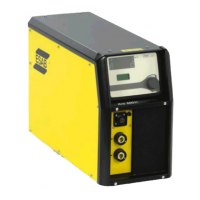
Technical specifications for the Arc 4000i welding machine.
Explanation of wiring diagram conventions and component naming.
List and brief descriptions of components used in the wiring diagrams.
Specific wiring diagram for Mig U4000i (serial 803-xxx-xxxx).
Specific wiring diagram for Mig 4000i (serial 803-xxx-xxxx).
Specific wiring diagram for Tig 4000i (serial 803-xxx-xxxx).
Specific wiring diagram for Arc 4000i (serial 803-xxx-XXXX).
Description and function of the AP2 interference suppressor board.
Explanation of the MMC module's role in machine control.
Description and function of the 2AP1 EMC interference suppressor board.
Explanation of the cooling unit's function and operation.
Detailed explanation of the power module's function and components.
Explanation of the 20AP1 control board's functions and features.
Explanation of the 20AP2 relay board's functions and connections.
How faults are recorded and indicated by unit numbers.
Table listing fault codes, descriptions, and affected units.
Detailed explanation of fault codes specific to the power source.
Explanation of Electrostatic Discharge and its effects.
Information on antistatic kits, ESAT, and special tools for service.
Procedures for dismantling and common pitfalls to avoid during service.
Method for checking the health of IGBT transistors.
Instructions for correctly mounting components on the heat sink.
Procedures for soft starting and verifying gate pulses.
Checking overvoltage and undervoltage protection threshold values.
Calibrating current sensor signal and arc voltage feedback.
Essential safety warnings and professional installation requirements.
Requirements for mains power connection and wire feed unit connectivity.
Connection details for the Mig U4000i model.
Step-by-step guide for powering on the welding equipment.
Instructions for cleaning the air filter of the power source.
Procedure for refilling the cooling system with coolant.
| Brand | ESAB |
|---|---|
| Model | Aristo Arc 4000i |
| Category | Welding System |
| Language | English |