Do you have a question about the ESAB AristoFeed 30 4 Series and is the answer not in the manual?
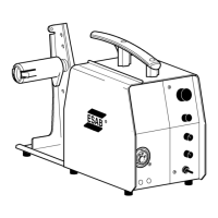
Overview of the wire feeders and manual contents.
List and brief explanation of electrical components used in the system.
Description of the control panel options and their functions.
Details of AC/DC supplies, voltage monitoring, and fault codes.
How the welding gun switch initiates the start/stop sequence.
Microprocessor control mechanism for the gas valve operation.
Explains motor power, PWM control, current monitoring, and braking.
Process for monitoring wire feed speed and detecting deviations.
Details on the dynamic braking circuit using optocoupler and resistors.
Functionality and input signals for the pulse generator.
Microswitch sensing of water-cooled gun connection for pump activation.
Information on future implementation for wire and gas supply monitoring.
Description of the CAN bus driver and its role in system communication.
Describes the power-up sequence and status indications via LEDs.
Troubleshooting steps for CAN communication failures.
Method used to sense arc voltage via filler wire and motor.
Usage of specific terminals for push pull and other I/O functions.
Details on power supply and voltage regulators for later board versions.
Monitoring of +60V, +24V, and +15V supplies and associated faults.
Operation of the welding gun switch for start/stop control.
How the microprocessor controls the gas valve.
Motor control, current monitoring, and braking for the drive stage.
Function of the pulse generator and tachometer inputs.
Monitoring status of water connection for pump activation.
Information about preparation for wire and gas monitoring features.
Details on the CAN bus driver and its role in system communication.
Troubleshooting procedures for CAN communication issues.
Method of sensing arc voltage for measurement.
Usage of terminals for push pull options and general I/O.
Wiring and configuration for MiggyTrac/RailTrac options.
Connection and configuration for pull motor welding guns.
Layout of CAN adapter and filter boards.
Table listing fault codes, their descriptions, and affected units.
Detailed explanations for specific fault codes and troubleshooting actions.
Precautions and methods for preventing Electrostatic Discharge damage.
Description of service kits for maintenance and software updates.
General safety guidelines for operating welding equipment.
Guidelines for safely lifting and mounting the wire feed unit.
Importance and placement of terminating resistors for CAN bus.
Procedure for connecting multiple wire feed units to the system.
Identification and function of external connections and controls.
Specifics of the water connection system and pump operation.
Procedure for adjusting pressure rollers for optimal wire feed.
Recommendations for regular inspection and cleaning of the unit.
Procedure for adjusting the braking torque on the wire feed hub.
Advice on cleaning and replacing wear parts for the welding gun.
| Brand | ESAB |
|---|---|
| Model | AristoFeed 30 4 Series |
| Category | Welding System |
| Language | English |