28
4.4.1 Endring av bueoppstart
KAPITTEL 4 BRUK
1. Fjern adkomstpanelet i øvre høyre hjørne på frontpanelet. Pass på å sette dette panelet tilbake etter at justeringene er
utført.
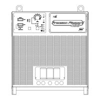
2. Finn SW1 og PCB1 og skyv begge vippebryterne ned for å sette bueoppstarttid AV (utkoplet). Skyv begge bryterne opp
for å sette bueoppstarttid PÅ (innkoplet). (Hvis den ene bryteren er opp og den andre ned, anses bueoppstarttiden å
være innkoplet).
4.4.2 Justering av dveletids-timeren for bueoppstart
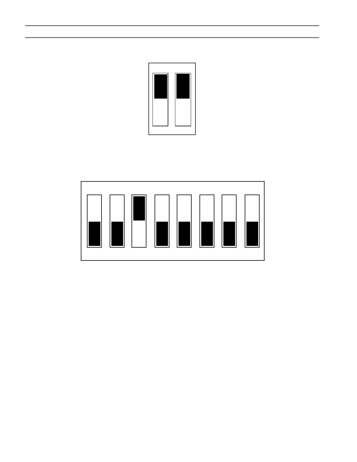
Dveletiden styres av bryterposisjonene 1-4 på SW2 på PCB1. Når en bryter settes til posisjon PÅ, legges dens verdi til den
fabrikkinnstilte minimumstiden 10 ms.
Bryter nr. 1 = 10 ms dveletid
Bryter nr. 2 = 20 ms dveletid
Bryter nr. 3 = 40 ms dveletid
Bryter nr. 4 = 80 ms dveletid
Standardinnstilling er med bryter 3 satt til PÅ, tilsvarende 40 ms + 10 ms (minimum) = 50 ms
4.4.3 Justering av minimum startstrøm
Minimum startstrøm styres av bryterne i posisjonene 5-8 på SW2 på PCB1. Når en bryter settes til ON, legges dens verdi til
den fabrikkinnstilte minimumsstrømmen 3 A.
Bryter nr. 5 = 25 A minimum startstrøm
Bryter nr. 6 = 12 A minimum startstrøm
Bryter nr. 7 = 6 A minimum startstrøm
Bryter nr. 8 = 3 A minimum startstrøm
Standardinnstilling er med 5, 6, 7 og 8 satt til ON (opp), tilsvarende 0 A + 0 A + 0 A + 3 A = 3 A
Standard fabrikkinnstillinger vist
Standard fabrikkinnstilling vist.
SW1
PÅ
AV
PÅ
AV
38
4.4.1 Enable/Disable Arc Initiation Conditions
SECTION 4 OPERATION
1. Remove access panel on the upper-right corner of the front panel. Be sure to replace this panel after adjustments have
been made.
2. Locate SW1 and PCB1 and push both rocker switches down to disable. To enable push both switches up. (If one switch
is up and the other is down, arc initiation time is considered on.)
4.4.2 Adjusting Arc Initiation Dwell Timer
Dwell Time is controlled by selections of positions 1 through 4 of SW2 on PCB1. When a switch is pushed on, its value is
added to the minimum dwell time of 10 msec.
Switch #1 = 10 msec dwell time
Switch #2 = 20 msec dwell time
Switch #3 = 40 msec dwell time
Switch #4 = 80 msec dwell time
The default setting is with switch #3 on. 40 msec + 10 msec (minimum) = 50 msec
4.4.3 Adjusting the Minimum Start Current
Minimum Start Current is controlled by selection of positions 5 through 8 of SW2. When a switch is pushed on, its value is
added to the factory set minimum value of 3A.
Switch #5 = 25A min. start current
Switch #6 = 12A min. start current
Switch #7 = 6A min. start current
Switch #8 = 3A min. start current
Default setting is with 5, 6, 7 and 8 off (down) 0A + 0A + 0A + 3A = 3A
Factory default settings shown
Factory default setting shown.
SW2
1 2 3 4 5 6 7 8