50
three leads
SECTION 6 TROUBLESHOOTING
REPLACEMENT:
A. Thoroughly clean any thermal compound from the heat sink and the modules. Any foreign material trapped between
the module and heat sink, other than an appropriate thermal interface, can cause module damage due to over heat-
ing.
B. Inspect the thermal (interface) pad, P/N 951833, for damage. A crease or deformity can prevent the module from seat-
ing properly, impeding the heat transfer from the module to the heat sink. The result can be module damage due to
over heating.
If a thermal pad is not available, a heat sink compound such as Dow Corning® 340 Heat Sink Compound may be used. It’s
a good idea to mount all paralleled modules located on the same heat sink using the same thermal interface. Dierent
interfaces can cause the modules to operate at dierent temperatures resulting in un-equal current sharing. The imbal-
ance can shorten module life.
C. Place a thermal pad, and an IGBT module on the heat sink. Carefully align the holes in the thermal pad with the heat-
sink and module holes. If heat sink compound is used in place of a thermal pad, apply a thin coat of even thickness to
the metal bottom of the module. A thickness of 0.002” – 0.003” (0.050mm – 0.075mm) is optimum. Too much com-
pound impedes heat transfer from the module to the heat sink resulting in short module life due to over heating.
D. Insert the four M6 mounting bolts, but do not tighten. Leave them loose a few turns. Be certain that the threads from
the mounting bolts do not bend the edges of the thermal pad clearance holes. A bent thermal pad can prevent the
module from seating properly, impeding the heat transfer from the module to the heat sink. The result can be module
damage due to over heating.
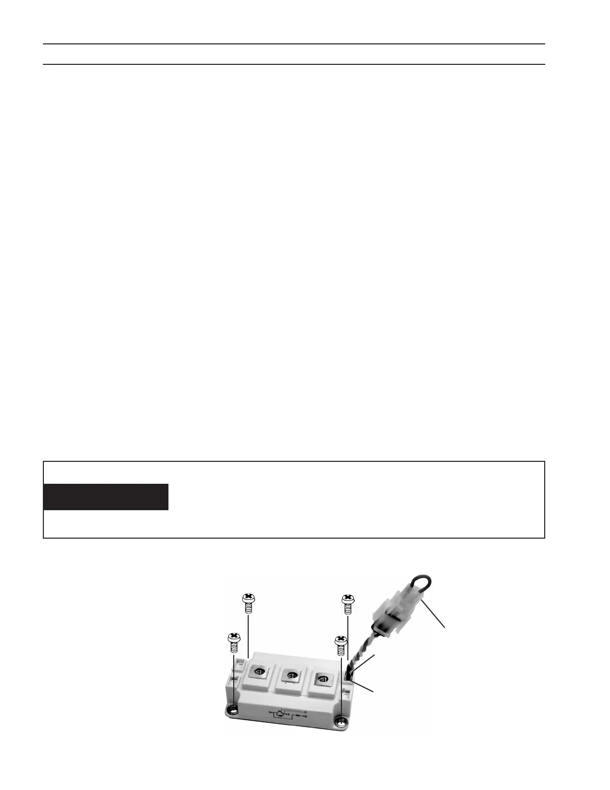
E. Partially tighten the four mounting bolts a little more than nger tight in the order: A-B-C-D. See gure below.
F. Fully tighten, in the same order above, to a torque of 35 – 44 in-lbs (4.0 – 5.0 N-M). See gure below.
G. Install the bus plates and bus bars. Be careful that the sheets of insulation separating the bus plates are still in their
original positions. It’s a good idea to tighten the mounting hardware only after getting it all started. Torque the M6
module terminal hardware to 35 – 44 in-lbs (4.0 – 5.0 N-M).
H. Remove the jumper plugs from the module gate lead plugs, and plug into the appropriate plugs from the PWM/Gate
Drive PC Board. See Caution below.
I. Replace the top panel.
The module gate plugs must be plugged into the PWM/Gate
Drive PC Board whenever the power source is in operation.
Failure to plug them in will result in damage to the module and
possible damage to the torch.
CAUTION
Four-Point Mounting Type
Partial tightening - A
➜B➜C➜D
Fully tightening - A
➜B➜C➜D
A
D
C
B
1
2
3
6 (RED)
7 (WHT)
Key Plug
Position 1 (RED)
1 - IBGT Collector, Free Wheeling
Diode (FWD) Anode
2 - IGBT Emitter
3 - FWD Cathode
6 - IGBT Gate
7 - IGBT Emitter