51
6.4.3 Power Shunt Installation
Instability or oscillation in cutting current can be caused by im-
proper dressing of shunt pick-up leads.
Poor torch consumable life will be the result.
CAUTION
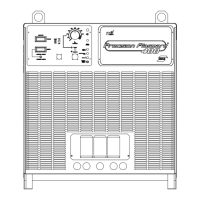
Terminals parallel
to bus bars
There are two cables that attach to the shunt pick-up points:
a two conductor cable drives the ammeter
a three conductor which provides the current feedback signal to PCB1 (control PCB).
Dressing of the 2 conductor cable is not critical.
The following is the dressing procedure for the 3 conductor cable.
• The breakout point should be physically at the middle of the shunt. The breakout point is the place
where the conductors exit from the outer insulation jacket.
• The black and clear insulated wires must be kept next to the shunt and under the cable ties.
• The wire terminals for the black and clear insulated wires should be oriented in parallel with bus bars
as shown.
SECTION 6 TROUBLESHOOTING
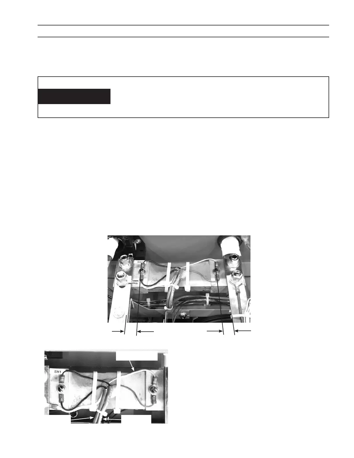
clear insulation
two leads
three leads
• It is important to have the barrels of the black
and clear insulated wires, from the three lead
cable, be pointing in opposite directions.
• The third wire attaches to the bus bar on the left
with the shunt mounting hardware. Orientation
of this wire is not critical.