− 88 −
fja4i1ea
Mains connection
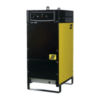
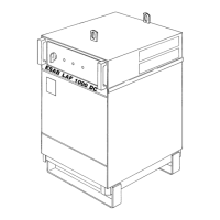
LAF 1000
50 Hz 60 Hz
Voltage V 400 415 500 400 440 550
Current A
100%
60%
64
80
64
80
52
65
64
80
64
80
52
65
Cable area mm
2
4 x 16 4 x 16 4 x 16 4 x 16 4 x 16 4 x 16
Fuse, slow A 63 63 63 63 63 63
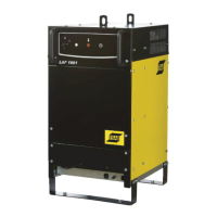
LAF 1000M 50 Hz 60 Hz
Voltage V 230 400 415 500 230 400 440 550
Current A
100%
60%
111
138
64
80
64
80
52
65
111
138
64
80
64
80
52
65
Cable area mm
2
4x50 4 x 16 4 x 16 4 x 16 4x50 4 x 16 4 x 16 4 x 16
Fuse, slow A 125 63 63 63 125 63 63 63
3.4 PC board
DIP switches
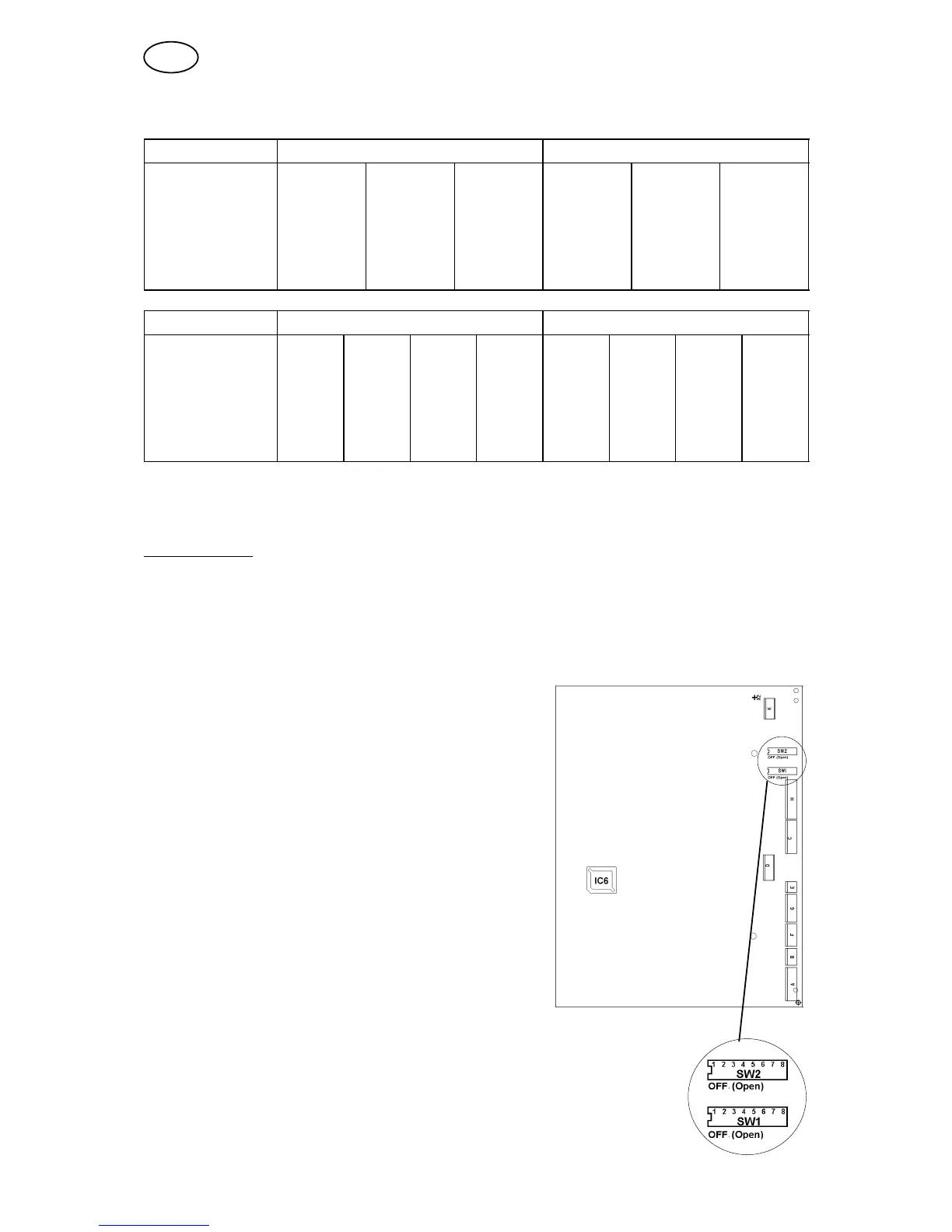
The PC board (AP1) has two DIP switches (SW1 and SW2) which are preset on
delivery. The settings are not to be changed.
When spare parts are supplied the settings of the DIP switches must be checked
(and set, if necessary) before fitting the PC board into the welding power source.
S DIP switch SW1
To make the communication with the
A2−A6 Process Controller (PEH) work
DIP switch 1 (SW1) must be set.
S DIP switch SW2
DIP switch 2 (SW2) must be set in order to
inform the A2−A6 process controller (PEH)
about the rating of the power source that is
connected.
Setting of DIP switch SW1
S Set pole 6 to “OFF“ position and all other
poles to “ON“.
Setting of DIP switch SW2
S Set pole 3 to “OFF“ position and all other
poles to “ON“.
Welding power source program
The welding power source program is stored in the flash
memory IC 6. The capsule is fitted in a holder and is
replaceable.
GB


 To Next Page