21
Before making electrical input connections to the weld-
ing machine, “Machinery Lockout Procedures” must be
employed. If the connections are to be made from a line
disconnect switch, the switch must be padlocked in the
o position. If the connection is made from a fusebox,
remove the fuses from the box and padlock the cover
in the closed position. If locking facilities are not avail-
able, attach a red tag to the line disconnect switch (or
fuse box) to warn others that the circuit is being worked
on. If the plug-cap is used, (see 3.2B) remove plug from
receptacle.
3.2.1 Input Electrical Requirements
Models of this welding machine are designed to be oper-
ated from 208/230, or 208/230/380/400/460/575 volts single
phase 50/60 Hz, depending on model. The primary input
voltage requirements are shown on the welding machine
nameplate.
3.2.2 Input Conductor Connections
The input power cord on 208/230 Volts primary input model
is provided with an attachment plugcap. The plugcap will
mate with a standard 250 Volts, 50 Ampere receptacle
conforming to NEMA 6-50 R conguration.
The 208-575 volt primary input model must be wired to a
separately fused disconnect or circuit breaker of the size
listed in Table 3.1. This disconnect or breaker can be wired
to a single phase system or to two conductors of a three
phase system. A third conductor for grounding must also be
connected between the disconnect and the receptacle.
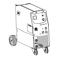
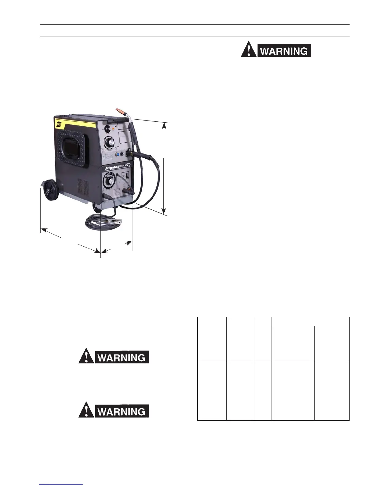
3.1 LOCATION (Figure 3.1)
Proper installation permits free air movement into and out
of the unit and minimizes exposure to dust, dirt, moisture,
and corrosive vapors. A minimum of 18 inches (46 cm)
unrestricted space must be maintained between the rear
panel and the nearest obstruction.
32.25"
19.50"
40.00"
CAUTION: Do not place any ltering device over the
air intake passages of the unit. This would
restrict air intake and cause an overheating
condition and possible failure. Warranty is
void if any type of ltering device is used.
If a forklift vehicle is used for lifting the unit, be sure that
the lift forks are long enough to extend completely under
the base.
Do not operate the machine without the running gear
installed.
3.2 ELECTRICAL INPUT CONNECTIONS
A line disconnect switch must be installed in the input circuit
to the welding machine. This is to provide a safe means to
completely remove all electrical power from the welding
machine whenever it is necessary to perform service on the
unit. (See Figure 3.2A.)
SECTION 3 INSTALLATION
Figure 3.1 Dimensions
Recommended
Full Primary
Primary Load Input Ground
Input Line Fuse Conductor Conductor
Volts Amperes Size Size Size
208 66 90 6 8
230 61 80 8 8
380 37 50 10 10
380 (50Hz) 38 50 10 10
400 36 50 10 10
400 (50Hz) 36 50 10 10
460 30 40 12 12
575 25 35 12 12
TABLE 3.1 Input Conductor and Fuse Size
OPTIONAL
DIGITAL METER
MODULE
OPTIONAL
BURN BACK
MODULE
 Loading...