10
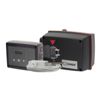
The mounting kits needed for ESBE mixing valves are supplied with the controller.
Connect up the actuator controller and mixing valve as set out in the brief description
provided on page 2.
The controller can also be used for other makes of mixing valve using various mounting
kits that can be ordered. Installation instructions will be enclosed with the mounting kit.
Safety information: Power supply must be switched off completely before work is
started on the control and connected loads.
Please note: The controller replaces in no way safety devices. Precautions such as
frost, scald and overpressure protection, etc., must be provided in the installation if
necessary.
The controller must only be installed by a qualified electrician in accordance with stan-
dards and/or local regulations.
The 90C controller should be wired up in the following order:
1 Pipe sensor (S2):
The sensor is prewired, with the cable being labelled “Flow Pipe Sensor”, and should
be secured in a suitable position on the heating circuit’s flow pipe using the pipe clip
provided. To make sure that the correct temperature is registered, the sensor should be
surrounded with pipe insulation.
2 Outside sensor (S1):
Mount the outside sensor in a shady position out of the wind on the north side of the
building.
Connect the cable labelled “Outside Sensor” in the sensor box – polarity does not
matter in this case. Depending on the inertia of the heating system, set the back of
the sensor box into the brickwork if necessary in order to take the residual heat of the
building into account.
3 Circulation pump: Warning: 230 VAC
If the circulation pump is to be operated via the controller, remove the three safety
terminals from the preconnected cable labelled “Pump” and connect the cable to the
circulation pump as follows:
Green/yellow: Earth PE
Blue: Neutral N
Brown: Phase L
Please note: If the pump is not connected, the electrician should remove the cable.
4 Power supply connection: Warning: 230 VAC
Plug the preconnected cable labelled “power supply” into a 230 V / 50 Hz socket outlet
with earthing contact. Wiring:
Green/yellow: Earth PE
Blue: Neutral N
Brown: Phase L
5 Room sensor option (S3)
If a room sensor is required, it should be connected as follows:
Strip a maximum of 40 mm of insulation from a 2x0.75 mm² cable and insert the end of
the cable through the free lead-in on the underside of the actuator cover. Connect the
cable to the two free terminals in the black cover – polarity does not matter in this case.
Once the unit has been switched on, it is ready for operation and will go into summer or
winter mode depending on the outside temperature. In summer mode the mixing valve
is closed completely and the circulation pump is switched off. The red LED then lights
up to indicate standby mode.
In winter mode the circulation pump is activated and the actuator moves the mixing
valve into position.
When the controller is switched on, it loads an internal factory program, enabling the
unit to run with standard parameters/basic settings once the internal clock has been
set. To set the controller for the particular heating system, see section Menu navigation.
If necessary, the mixing valve’s direction of rotation can be changed acc. to specified in
section Menu navigation - ”06 Special Functions” menu.
Manual mode (see section Emergency/Manual mode) can be used to check that the
pump is being switched on and the mixing valve is being opened and closed properly.
Do not open the unit until it has been disconnected!
The unit is protected by a 2A miniature fuse. The fuse can be checked and changed if
necessary once the housing cover has been opened.
A sensor defect in the case of an open/short circuit at the outside or flow pipe sensor
will be indicated by the red LED flashing and an error message on the display. The
temperature sensors can also be checked for correct functioning with an ohmmeter
using the table as a guide.
Temperature-resistance table for KTY81-210 sensors:
T./°C -10 0 10 20 30 40 50 60 70 80
R./ 1495 1630 1772 1922 2080 2245 2417 2597 2785 2980
Fitting the actuator control
Electrical connection
Start-up
What to do if there is a malfunction