C
20
When cung the hole in the outside wall, be mindful of how the
installaon of the Horizontal Power Flue Wall Terminal will be
nished; the installaon must be weatherproof.
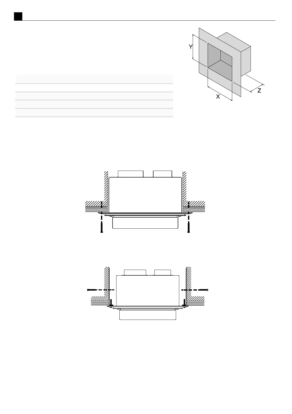
Ideal hole/cavity size for horizontal Power Flue
Without Side Brackets With Side Brackets
X 298mm 360mm
Y 298mm 298mm
Z 175mm
The Horizontal Power Flue Wall Terminal can be aached to the wall in two ways:
A) By aaching the oponal wall terminal installaon brackets to the sides of the cavity and aaching the
Horizontal Power Flue Wall Terminal to these, from the front:
B) From the front of the terminal:
Aach the Ø100mm and Ø75mm exible aluminium ues to the spigots on the rear of the Horizontal Power
Flue Wall Terminal using the hose band clamps supplied. Plug the Power Flue electrical cable into the back of the
Horizontal Power Flue Wall Terminal.
For informaon on the PolyPro ue, see the installaon manual which is supplied with the ue components.
Ensure that the electrical cable is rmly secured to the wall terminal or building to prevent damage or
disconnecon if pulled.
A
B