C
22
C4
The UVP is designed to have the enclosure containing the fan unit mounted externally. Escea recommends this
install for a UVP powerue; an example is shown below.
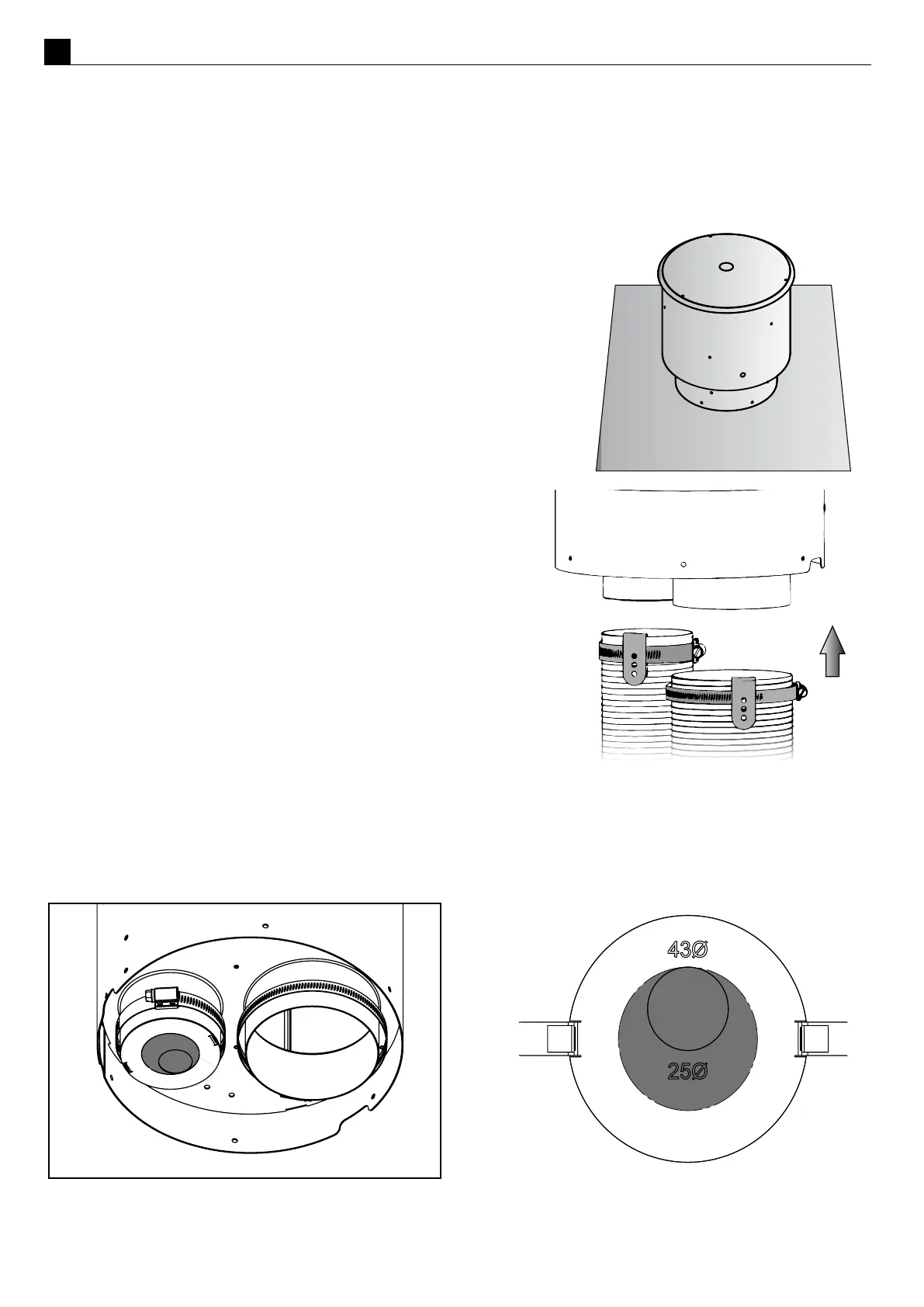
Note: When installing the unit onto a ue liner, ensure the length of ue liner above the roof is the minimum
required length. ENSURE the Ø43mm restricon plate is installed on the inlet.
The cowl surround should be xed in place as shown right.
Mount the UVP kit to the top of a chimney ashing plate or penetrate the
roof with an oponal ue liner accessory and t the UVP kit over the ue
liner, sealing the penetraon with a deckte or similar ashing.
Ensure the terminal is vercal and rigidly mounted and the exi ue
aached below is xed to the terminal spigots using the supplied hose
clamps and aid clips.
Place the clamp over the exi ue and the clip over this. Make
sure the exi tube has been stretched out as far as possible
where the hose band clamps are going to be aached (not sll
compressed). Slide the exi tube over the spigot and hold it in
place by drilling one hole through the spigot using the clip guide
hole and riveng the three components together.
Note: If this install is unpraccal for your situaon see
informaon regarding an internal install of the UVP, go to secon
C5 on page 23.
The new DF700 and DF960 res need to be paired with a specic ue restrictor to work as intended, some UVP
units will already have this installed, if that is the case then all that is needed is to pop out the restrictor shown
in gray so that only the “43” is showing.