13
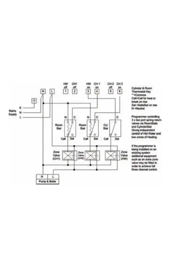
Example circuit diagram for a typical installaon is shown below.
This diagram is schemac and should be used as a guide only.
Please ensure that all installaons comply with the current IEE
regulaons. For reasons of space and clarity the diagram has been
simplified. For instance some Earth connecons have been omied.
Other control components shown in the diagram i.e. Valves, Room
Stats etc are general representaons only. However, the wiring
detail can be applied to the corresponding model of most manufac-
turers e.g. Horstmann, Honeywell, Danfoss Randall, Drayton, ESi
Controls etc.
1. Remove old programmer from its back plate mounng loosening
any securing screws as dictated by its design.
2. Check compability of exisng back plate & wiring arrangement
with that of the new programmer. See online Programmer Replace-
ment Guide for direcon.
3. Make all necessary changes to back plate & wiring arrangement
to suit new programmer.
Exisng Installaons
New Installaons