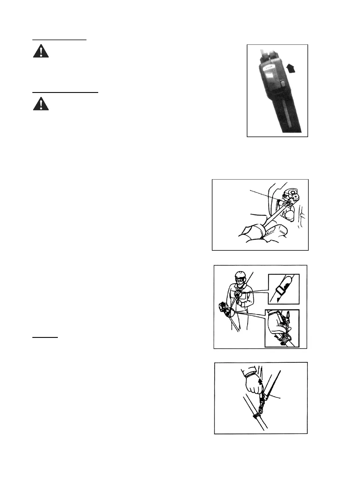
Stopping the engine
WARNING! The cutting attachment will continue rotating after
the engine is switched off.
1. Cool the engine by allowing it to idle for 2–3 minutes.
2. Slide the ignition switch to ”O” (STOP) position (Fig. 17).
Adjusting the carburetor
WARNING! The cutting attachment must never rotate at engine
idle speed. The engine must return to idle speed whenever the
throttle trigger is released. Idle speed is adjustable and must be
set low enough to permit the engine clutch to disengage the cut-
ting attachment when throttle trigger is released.
IMPORTANT! A wrong adjustment may cause damage the machine. If the
engine does not run well after adjusting the carburetor, contact an authorized
service center.
Idle adjusting screw
This is the screw (Fig. 18) to adjust the engine rotation speed
when the throttle lever is set to the lowest speed position. If you
turn the screw right (clockwise), rotation speed increases, and
when turning left (counterclockwise) it decreases. In case the
blade continues to rotate or engine stops when you return the
throttle lever completely to the original position, make readjust-
ment.
1. Start the engine and allow it to idle 2–3 minutes or until it
warms up.
2. If the cutting attachment rotates at engine idle, reduce idle
speed by turning the idle adjusting screw counterclockwise as
necessary.
NOTE! If a tachometer is available, use it to set the engine
idle. Standard idle speed is 3000 ± 200 rpm.
3. If the engine is stalling and won’t idle, increase idle speed by
turning the idle adjusting screw clockwise.
NOTE! The mixture of the carburetor cannot be adjusted.
The strap
To wear the strap (Fig. 19)
1. Hook the strap hook to the hanger on the outer tube.
2. Wear the strap so that the hook stays at your right hand side.
3. Adjust the length of the strap so that you can hold and oper-
ate the machine comfortably.
Emergency release (Fig. 20)
In case of emergency, strongly pull the white tab at the hook.
The machine will be released from the strap.