1 Overview
1.2 Pin Description
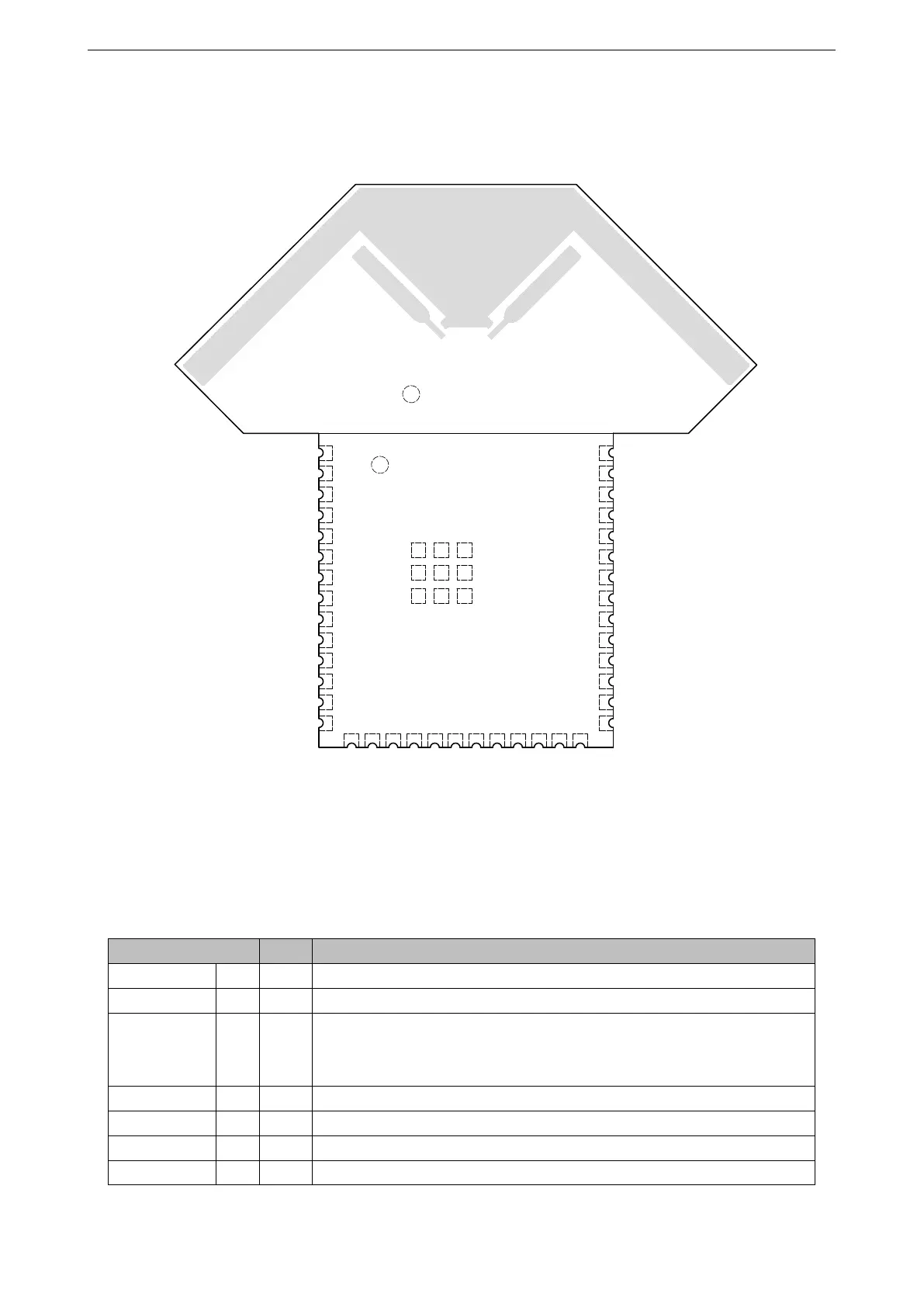
The pin diagram below shows the approximate location of pins and the two antennas on the module.
1
2
3
4
5
6
7
8
9
10
11
12
13
14
GND
3V3
SENSOR_VP
SENSOR_VN
IO34
IO35
IO32
IO33
NC
IO26
IO27
IO14
IO12
EN
40
39
38
37
36
35
34
33
32
31
30
29
28
27
15
16
17
18
19
20
21
22
23
24
25
26
NC
GND
IO13
NC
NC
NC
NC
NC
NC
IO15
NC
NC
GND
IO23
IO22
U0TXD
U0RXD
IO21
NC
IO19
IO18
IO5
IO17
IO16
IO4
IO0
GND GND GND
GND
43
GND
GND
GNDGNDGND
42
41
IO2
IO25
Top View
Antenna 1
Antenna 2
Figure 1: Pin Layout (Top View)
The module has 41 pins and two test points. See pin definitions in Table 2.
Table 2: Pin Definitions
Name No. Type Function
2
GND 1 P Ground
3V3 2 P Power supply
EN 3 I
High: On; enables the chip
Low: Off; the chip powers off
Note: Do not leave the pin floating.
SENSOR_VP 4 I GPIO36, ADC1_CH0, RTC_GPIO0
SENSOR_VN 5 I GPIO39, ADC1_CH3, RTC_GPIO3
IO34 6 I GPIO34, ADC1_CH6, RTC_GPIO4
IO35 7 I GPIO35, ADC1_CH7, RTC_GPIO5
Cont’d on next page
Espressif Systems 5 ESP32-WROOM-DA User Manual v0.5

 Loading...


