1 Overview
Table 2 – cont’d from previous page
Name No. Type Function
2
NC
3
42 — —
GND 43 P Ground
1
For peripheral pin configurations, please refer to ESP32 Series Datasheet.
2
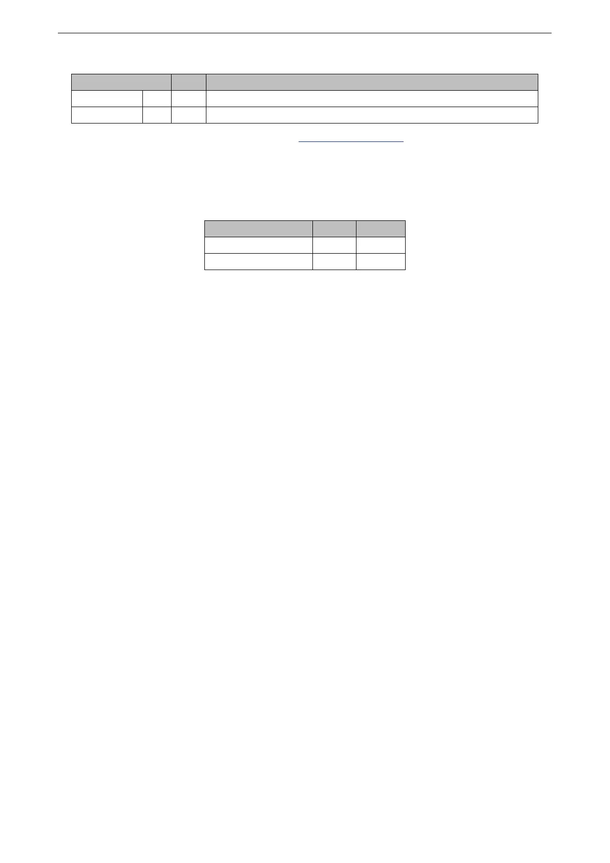
GPIO2 and GPIO25 on the ESP32-D0WD-V3 chip are designed as test points to control RF Switch.
The two pins are not led out to the module. To select the working antenna, (Antenna 1 or Antenna 2),
configure GPIO2 and GPIO25 as follows:
Table 3: Select Working Antenna
Working Antenna GPIO2 GPIO25
Antenna 1 High Low
Antenna 2 (by default) Low High
Espressif Systems 7 ESP32-WROOM-DA User Manual v0.5

 Loading...


