Fire Alarm Computer 8000C / M
Page 97
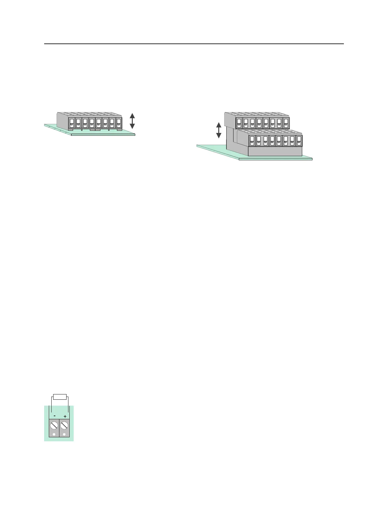
Connection terminals
To simplify installation, you may detach the connection terminals from the field device module.
This is done by carefully lifting the screw terminal from the field device module using a suitable
tool (e.g. screwdriver). After connecting the wires, fit the terminal strip back onto the plug-in
contacts on the field device card.
Fig. 38: Connection terminals Fig. 39: Fire department operating panel
11.1 Connection of the micro module
Eight connecting terminals are provided for the micro module slot of the Field device module. The
actual connection of the eight terminals depends on the type of module used. The various
configurations for the different micro modules are described in the
micro modules
section.
☞
If an essernet
®
micro module is used, this module may only be inserted into the micro
module slot of the basis module. The essernet
®
micro module requires adaptation of the
terminal card on the basis module by means of jumpers X11-14.
11.2 Primary loop input Pri+/Pri-
Monitored primary loop input Pri+/Pri- (terminal X11) has the purpose of monitoring CPU failure in
the essernet
®
system. These terminals are used, for example, to connect the common fire relay of
another fire alarm control panel. In the event of trouble in the essernet
®
micro module, a fire alarm
signal may still be sent via the relay contact to the primary loop input of this control panel. The
alphanumeric display at this fire alarm control panel will then show the message "Prim. loop fire" in
the event of an incident occurring.
The primary line input can be switched off or on and reset via the corresponding primary line
number. The primary line number of this input is determined as follows:
Primary loop No.: XX24 (XX = panel no. 01-31)
R*
= monitored end-of-line resistor R =10 k
Ω
R= 10 k
Ω ⇒
normal status
R= 5k
Ω ⇒
Fire alarm, display
"Prim. loop fire"
R= 1k
Ω ⇒
trouble
Field device module / extension modu