ETC Setup and Connect Guide
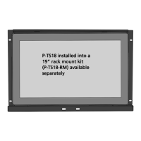
Paradigm 18 inch Touchscreen
P-TS18 Touchscreen Page 2 of 15 ETC
Table Top Stand Mounting
The table top stand accessory is provided with the Paradigm 18 inch Touchscreen.
1: Locate the table top stand and installation hardware in the main packaging with the touchscreen.
2: Align the table top stand to the back of the touchscreen. Reference the graphic above for
clarification.
3: Secure the stand to the touchscreen using two screws (provided).
4: Locate the international power supply and cables from the touchscreen accessory box.
5: Insert the power supply round plug into the Touchscreen “12V DC IN” receptacle, located on the
back of the unit.
6: Using the appropriate power cable adaptor that is required for your region, insert the receptacle end
into the power supply and the plug end into the power source.
7: Connect an Ethernet cable (not provided) between the P-TS18 “Net3 Network” interface, which is
the left-most RJ-45 connector while viewing the back, and the network switch that is also connected
to the Paradigm Central Control Server (P-CCS).