ETC Setup Guide
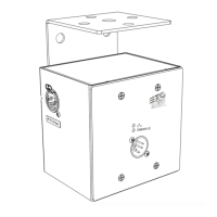
Analog IO Gateway (Rack-Mount)
Analog IO Gateway (Rack-Mount) Page 2 of 5 ETC
Electrical Specifications
The gateways are powered by either auxiliary power or Power over Ethernet (PoE).
Auxiliary power input rated voltage of 12-24 VDC, 15 W maximum, Polarity Independent
10/100Base-T, PoE power (IEEE 802.3af), Class 2
For auxiliary power, the gateway uses an external DC power supply (ETCpart# PS372, available
separately).
If you supply both PoE and auxiliary power, the gateway defaults to using auxiliary. If auxiliary
power is lost, the gateway will reboot and then begin using PoE.
Note:
If you are using an external power supply, it must be rated at a maximum of 15
watts.
Analog Inputs
24 VDCmaximum, can sense between 0–10 V (10 V, 100 mA utility supply provided)
0–10 V converted to 8-bit (0-255) digital values
Can withstand up to 24 VDC (registered as 255)
Relay Outputs
30 VDCmaximum voltage
0.5 A resistive load maximum
28VAR300 contactor rating
Analog Inputs and Relay Outputs
Wiring for your inputs and outputs are both done on 12-position screw clamp terminal blocks. When
connecting your wires, consider the following:
Strip length: 6 mm (0.25 in)
Torque: 0.5–0.6 Nm (4.4–5.3 lb-in)
Wire size: 0.2–1.3 mm
2
(24–16 AWG)
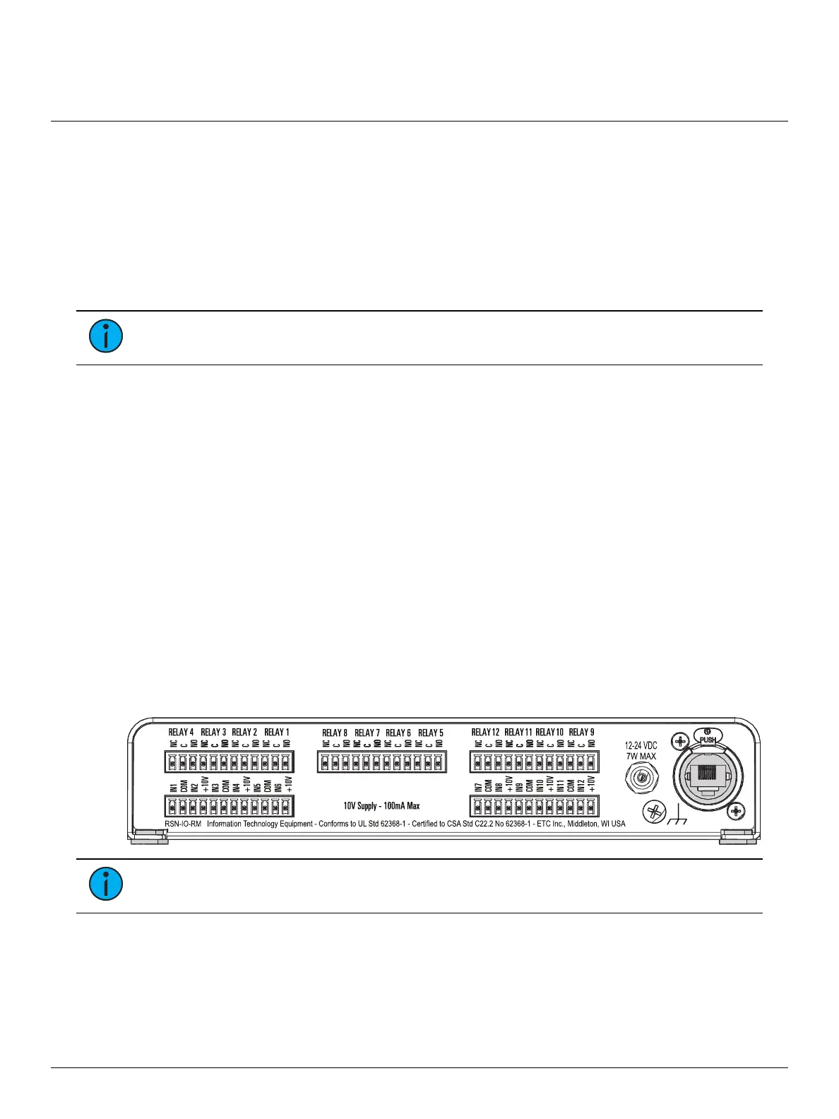
Reference the pinout diagram on the back of the gateway for wiring details:
Note:
The NO and NC terminals on the relays represent Normally Open and Normally
Closed, respectively
Once you have finished wiring, replace the connectors in their appropriate positions on the gateway.
 Loading...