10 CEM+ Sensor Rack Retrofit Manual
Step 6: Insert tabs in the side of the
rack.
Step 7: With the tabs fully inserted in the
sides of the rack, pull the
backplane towards the front of
the rack to line up the screw
holes in the upper side corners
to line up.
Step 8: Install one screw with a sleeve in each side upper-corner of the backplane.
Change out the AF Cards (if present)
Step 1: Remove the old AF cards (pull the plastic tabs)
Step 2: Address the new AF cards (mini-switches) as
shown below.
Step 3: Install the cards in the slots. Make sure they are
completely and securely seated. Card #1 at the
top, down to 4 at the bottom for SR48. (SR6, SR12
& SR24 have fewer cards. Always start with #1 at
the top.)
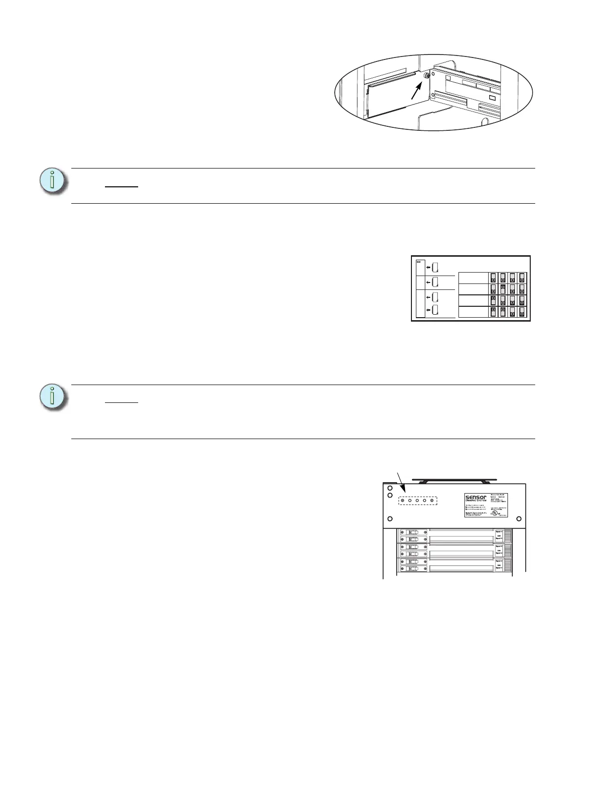
Change out the Beacon PCB
Step 1: Remove the two screws that hold the beacon PCB in the face of the rack.
Step 2: Pull the PCB down and around the rack
case. (The wire harness will only let it go
so far.)
Step 3: Note the orientation of the connector. and
unplug the wire harness from the old
Beacon PCB.
Step 4: Attach the wire harness to the new
beacon PCB with the connector in the
same orientation.
Step 5: Install the new beacon PCB (ETC Part #
7050B5109) with two screws (ETC Part #
HW222) (two new screws of the same type are provided in case the old ones get
damaged during the removal process).
Note:
You cannot use the old screws without the additional shoulder-sleeve as they will
block the CEM+ from being fully inserted.
Note:
Be sure to use a properly sized screw driver (#2 Phillips) and a good amount of
force as those screws are kept in place with a thread locker. Don’t worry about
damaging the existing screws (replacements are provided) or shearing off the
heads of the screws (the screw shanks are threaded into the PCB’s standoffs).
Screw with
sleeve
AF Card Addressing
Card 1
Card 2
Card 3
Card 4
S
W
1
S
W
2
S
W
3
S
W
4
1
SR6+
SR12+
SR24+
SR48+
2
3
4
Sensor+
New blue-LED
beacon PCB