2 The Retrofit 5
Section 2
The Retrofit
Preparation
Step 1: Use Sensor Configuration Editor and a SLTA to download and save the current
Sensor configuration out of racks for later reference.
Step 2: Turn off main power to the rack(s).
Step 3: Pull the modules out of the rack. Note and document the module’s order/
positioning in the rack for proper insertion and configuration later.
Step 4: Use a digital voltmeter and VERIFY that power is off by checking voltages for
all combinations between the phase bars, neutral and ground.
Remove the Old
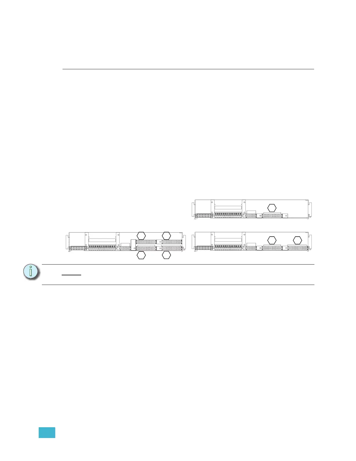
Step 1: Mark the edge connector of each dimmer output ribbon cable (1, 2, 3 & 4) as
illustrated below in the hexagons. There may be stickers on the ribbon cables
already, however these refer to cable length and not dimmer outputs. They
should not be used as a reference to these instructions.
Step 2: Document and/or label each wire that is currently landed on the J2 edge
connector.
Step 3: Unscrew the dimmer output edge connectors from the backplane metal.
Step 4: Carefully feed the dimmer output ribbon cables through the backplane.
Step 5: Examine each ribbon cable for any nicks or cuts due to backplane scrapes.
Step 6: Unscrew the power edge connector (J1). Remove it from the back plane by
sliding it out of the notch in the rack and carefully pushing it through the
backplane metal. This connector will be used in the upgrade.
Step 7: Unscrew the backplane metal from the rack. (One screw in each side upper-
corner - two screws total.) Discard these screws. Replacement screws with
thread locker are provided (ETC Part# HW377).
Note:
The order/layout of the dimmer output edge connectors is different on the CEM+
backplane.
1 2 3 4 5 6 7 8 9
10 11 12 13 14
1 2 3 4 5 6 7 8 9
10 11 12 13 14
1 2 3 4 5 6 7 8 9
10 11 12 13 14
CEM SR48 Ribbon Cable Layout
(1-24)
CEM SR6/12 Ribbon Cable Layout
(1-24)
(73-96)
(49-72)
(25-48)
1
1
3 4
2
(25-48)
(1-24)
CEM SR24 Ribbon Cable Layout
1 2
J1
J2 J3
J1
J2 J3
J1
J2 J3