14 CEM+ Sensor Rack Retrofit Manual
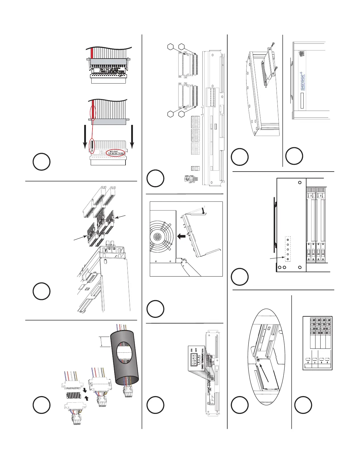
AF Card Addressing
Card 1
Card 2
Card 3
Card 4
S
W
1
S
W
2
S
W
3
S
W
4
1
SR6+
SR12+
SR24+
SR48+
2
3
4
Sensor+
DMX ADMX BDMX ThruBeacon
Power
CEM+ Ribbon Cable Layout
(1-24)
(73-96)
(49-72)
(25-48)
1
2
3
4
O
h
,
I
w
i
s
h
I
w
e
r
e
a
n
O
s
c
a
r
M
e
y
e
r
®
w
i
e
n
e
r
.
.
.
"Upper" Transition board
(7150B5007)
"Lower" Transition board
(7150B5006)
1-1/4" minimum
past both ends
Match red
wire to
pin-1 and
check for
correct
side up.
New blue-LED
beacon PCB
Assemble the power
harness adapter &
heat shrink it
5
Set the DMX
termination
8
Install backplane screws (2)
11
Install new beacon PCB
13
Install new beacon acrylic
14
Apply new
Sensor+
label
15
Address
AF cards
12
Make the power & data connections
10
Bend &
insert
the new
backplane
9
Identify the ribbon cable
transition cards for
correct use and placement
6
Mate the transition card(s) with the
correct ribbon cable connector.
Note the markings for proper
orientation to both the ribbon cable
and the backplane.
7