EasyManua.ls Logo

ETCR ETCR2000+ - User Manual

ETCR ETCR2000+
32 pages
Print Icon
To Next Page IconTo Next Page
Loading...

Questions and Answers

  • G
    garnerstevenAug 3, 2025
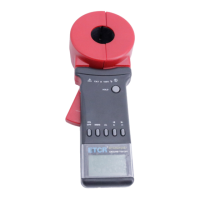
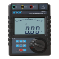
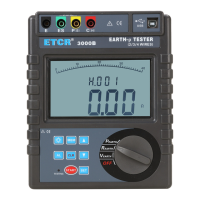
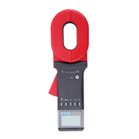
    What to do if my ETCR ETCR2000+ Test Equipment indicates an ERROR?
    • F
      fmejiaAug 3, 2025
      If your ETCR Test Equipment shows 'Err', large error results, or unstable readings, it could be due to several reasons. First, try replacing the batteries. If that doesn't solve the problem, check the jaw's contact surface for dust or oil and clean it. Another potential cause is poor jaw closure; try triggering the clamp multiple times and then rebooting the device. In some cases, the error may indicate a defective circuit component, and the PCB should be replaced. Finally, ensure you are following the correct measurement steps as outlined in the manual.
  • J
    Joshua ChapmanAug 9, 2025
    Why won't my ETCR ETCR2000+ button on?
    • J
      Jerry WigginsAug 9, 2025
      If your ETCR Test Equipment isn't powering on, start by checking the batteries. Ensure they are correctly installed with the right polarity and are not depleted. If the batteries are fine, inspect the battery contacts for any issues and replace them if needed. Confirm you're using the correct battery type. Also, test the battery harness for continuity and replace it if there's a break. Check the power button itself and re-assemble it if it's loose. Ensure the power plug has good contact, re-plugging or replacing it if necessary. In some instances, a defective circuit component on the PCB may be the cause, particularly if the current consumption is high; consider replacing the PCB.
  • J
    Jessica VincentAug 15, 2025
    Why is my ETCR ETCR2000+ Test Equipment incapable of measuring resistance?
    • J
      Johnny BarkerAug 15, 2025
      If your ETCR Test Equipment can't measure resistance, the battery might be low; replace it if the 'Low battery' indicator appears on the LCD. Ensure the instrument performs self-calibration before the test, following the manual to reboot and measure only after calibration completes. Check for the 'jaw-open' symbol on the LCD, which indicates poor jaw closure; trigger the clamp several times and reboot. Also, verify that the jaw's contact surface is clean from dust or oil. If these steps don't resolve the issue, a circuit component may be defective; in this case, consider replacing the PCB and readjusting the device.
  • M
    Margaret JohnsonAug 22, 2025
    What to do if my ETCR ETCR2000+ is incapable to hold reading?
    • C
      Carol SchaeferAug 22, 2025
      If your ETCR Test Equipment isn't holding readings, check if the HOLD button has come loose and re-assemble it. If the issue persists, the problem might be a defect of circuit component. In this case, replace the PCB.
  • V
    Virginia HillAug 27, 2025
    Why is my ETCR Test Equipment LCD Indication showing errors?
    • A
      Anthony KingAug 27, 2025
      If your ETCR Test Equipment's LCD is displaying errors such as missing segments, incorrect arithmetic points, or wrong units, it could be due to a few reasons. First, check the LCD connection wire for poor contact and try re-plugging or replacing the plug. If the problem continues, the LCD itself might be defective and need replacement. Also, ensure that the batteries have sufficient capacity and replace them if necessary. As a last resort, a defective circuit component could be the cause, requiring replacement of the PCB.

Summary

I. Attention

II. Brief Introduction

III. Specification

Model of Series

Lists different ETCR models, jaw sizes, resistance/current ranges, storage, and alarm functions.

Ranges and Accuracy of Measurement

Details measurement ranges and accuracy for resistance and current modes, including resolution.

Specifications

Provides detailed technical specifications including safety, dimensions, weight, battery, environment, and interfaces.

IV. Structure of Meter

V. Liquid Crystal Display

LCD Screen Layout

Explains the different symbols and indicators on the LCD screen.

Description of Special Symbols

Explains special symbols like "OL Ω", "L0.01Ω", "Er", low battery, MEM, MR, etc.

Examples Illustrated

Provides visual examples of various display readings and error messages for practical understanding.

VI. Operating Method

Boot Up Procedure

Details the steps and precautions for powering on the instrument and initial self-test.

Shutdown Procedure

Explains how to properly turn off the instrument, including auto-shutdown and manual shutdown.

Resistance Measurement

Guides on performing resistance measurements, including interpreting readings like "OL Ω" and "L0.01Ω".

Current Measurement

Details how to perform current measurements and understand readings like "OL A" and alarm indicators.

Data Lock, Release, and Storage

Explains how to lock, release, and store measured data, including memory capacity and indicators.

Data Access

Guides on accessing stored data, navigating through stored units, and handling cases with no stored data.

Alarm Settings

Instructions on how to turn alarm functions on/off and set critical alarm values for resistance and current.

Access to Alarm Critical Value

Describes how to check the previously set alarm critical values for resistance or current measurements.

Clear Data

Explains the procedure to clear all stored data and notes that data cannot be restored after clearing.

VII. Measurement Principle

Principle of Resistance Measurement

Explains the basic principle of measuring loop resistance using voltage and current coils.

Principle of Current Measurement

Explains the basic principle of measuring current using magnetic induction in the conductor.

VIII. Measurement Method of Earth Resistance

Multi-Point Grounding System Measurement

Describes how to measure earth resistance in multi-point grounding systems, including equivalent circuit.

Limited Point Grounding System Measurement

Details measurement for limited point grounding systems where grounding bodies are interconnected.

Single-Point Grounding System Measurement

Explains measurement for single-point grounding, including two-point and three-point methods.

IX. Bill of Loading

X. Parts List and Assembly Details

Parts List

Lists all parts with their names, part numbers, quantity, and remarks.

Assembly Details

Provides visual diagrams and instructions for assembling the instrument components.

XI. Troubleshooting

ETCR ETCR2000+ Specifications

General IconGeneral
BrandETCR
ModelETCR2000+
CategoryTest Equipment
LanguageEnglish

Related product manuals