EasyManua.ls Logo

ETCR ETCR2000E Plus - User Manual

ETCR ETCR2000E Plus
44 pages
Print Icon
To Next Page IconTo Next Page
Loading...

Questions and Answers

  • E
    egonzalezAug 16, 2025
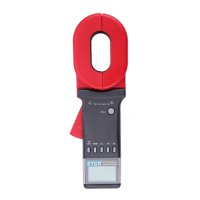
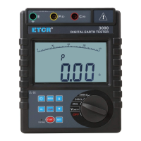
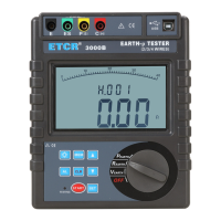
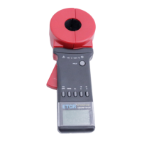
    What to do if my ETCR Test Equipment indicates ERROR?
    • S
      Stephen CoxAug 16, 2025
      If your ETCR Test Equipment displays “Err”, shows big error results, or the results are unstable, the possible causes include: * Insufficient battery capacity: Replace the batteries. * Contaminated jaw contact surface: Clean the surface. * Poor jaw closure: Trigger the clamp several times and then reboot. * Defective circuit component: Replace the PCB. * Incorrect measurement steps: Study the manual and follow it.
  • J
    James LewisAug 19, 2025
    Why won't my ETCR Test Equipment turn on?
    • A
      Ann RichardsAug 19, 2025
      If your ETCR Test Equipment doesn't turn on, it might be due to the following reasons: * No batteries: Insert the batteries. * Faulty battery polarity: Install the batteries with the correct polarity. * Insufficient battery capacity: Replace the batteries.
  • M
    moorejoshuaAug 22, 2025
    Why is my ETCR Test Equipment incapable of resistance measurement?
    • E
      Erica BanksAug 22, 2025
      If your ETCR Test Equipment is incapable of resistance measurement, it could be due to these reasons: * Insufficient battery capacity: Replace the battery when the 'Low battery' mark is displayed on the LCD. * Poor jaw closure, indicating 'jaw-open' symbol on LCD: Trigger the clamp several times and then reboot. * Contaminated jaw contact surface: Clean the surface. * Without self-calibration before test: Reboot and follow the manual, conduct measurement after self-calibration is finished. * Defect of circuit component: Check the above points first. If there is no problem, replace the PCB, and do re-adjustment.
  • S
    sheilaroweAug 25, 2025
    What to do if my ETCR Test Equipment LCD shows indication error?
    • A
      Amanda ThompsonAug 26, 2025
      If the LCD of your ETCR Test Equipment shows errors (chip of segment, arithmetic point, unit and so on), consider these potential causes: * Poor contact of LCD connection wire: Re-plug the LCD connect plug or replace the plug. * Defective LCD: Replace the LCD. * Insufficient battery capacity: Replace the batteries. * Defect of circuit component: Replace the PCB.
  • T
    Tyler BrownAug 27, 2025
    What to do if my ETCR ETCR2000E Plus Test Equipment is incapable to hold reading?
    • J
      Joshua BaileyAug 27, 2025
      If your ETCR Test Equipment is incapable of holding a reading, it might be due to: * HOLD button Depart from the position: Re- assemble the button. * Defect of circuit component: Replace the PCB.
  • R
    Regina CooperAug 30, 2025
    What to do if there is a defect of circuit component in my ETCR ETCR2000E Plus?
    • A
      Alan FisherAug 30, 2025
      If there is a defect of circuit component in your ETCR Test Equipment, especially if the current consumption is about 100mA or more at 6V of battery voltage due to a defect of PCB, replace the PCB.
  • J
    John BanksSep 2, 2025
    What to do if there is poor contact of power plug in ETCR ETCR2000E Plus Test Equipment?
    • J
      Javier WalshSep 2, 2025
      To solve the poor contact of the power plug in your ETCR Test Equipment, re-plug or replace the plug.
  • W
    wmillerSep 4, 2025
    What to do if the ON/OFF button departed in ETCR ETCR2000E Plus?
    • S
      Stephen CabreraSep 5, 2025
      To solve the issue of the ON/OFF button departure in your ETCR Test Equipment, re-assemble the button.
  • T
    Timothy TurnerSep 7, 2025
    What to do if there is a break in a battery harness of ETCR ETCR2000E Plus?
    • D
      davisjessicaSep 7, 2025
      To address a break in the battery harness of your ETCR Test Equipment, conduct a continuity test of the test lead. If there is no continuity, replace the battery harness.
  • M
    Michelle BakerSep 10, 2025
    What to do if there is a wrong battery type in ETCR Test Equipment?
    • K
      Kenneth LittleSep 10, 2025
      To fix the wrong battery type issue in your ETCR Test Equipment, replace it with the right type.

Summary

Attention and Safety Precautions

Safety Precautions

Essential safety guidelines for operating the clamp earth resistance tester.

Brief Introduction to the Tester

Product Features and Capabilities

Overview of the ETCR Multifunctional Clamp Earth Resistance Tester's key features and performance.

Technical Specifications

Model Series and Jaw Sizes

Details the different models and their corresponding jaw sizes.

Measurement Ranges and Accuracy

Specifies the accuracy and ranges for resistance and current measurements.

Detailed Technical Specifications

Covers resolution, data memory, interfaces, power, environment, and display details.

Structure of the Meter

Component Identification and Function

Identifies and explains the function of each part of the clamp meter.

Liquid Crystal Display (LCD) Information

LCD Screen Layout

Explains the various symbols and indicators displayed on the LCD screen.

Special Symbol Explanations

Details the meaning of specific symbols and error codes shown on the display.

Illustrated Measurement Examples

Provides visual examples of various measurement scenarios and their display outputs.

Function Zoom Table

Function Button Mapping

Summarizes the functions of the meter's buttons and their respective operations.

Operating Method

Booting Up the Device

Step-by-step guide on how to power on and initialize the clamp earth resistance tester.

Device Shutdown Procedures

Instructions on how to properly turn off the meter, including delayed shutdown.

Performing Resistance Measurements

Detailed steps for measuring earth resistance, including handling display indicators.

Performing Current Measurements

Guide to measuring current, including how to switch modes and interpret results.

Data Lock, Release, and Storage

Explains how to lock, release, and store measurement data, including memory full indications.

Accessing Stored Data

Instructions on how to retrieve and view previously stored measurement data.

Configuring Alarm Settings

Steps to enable/disable alarm functions and set critical alarm values.

Accessing Alarm Critical Values

How to view the previously set alarm critical values for resistance or current.

Clearing Stored Data

Procedure for deleting all stored measurement data from the device.

Uploading Data to PC

Instructions for connecting to a PC and using software for data monitoring and transfer.

Measurement Principle Explained

Principle of Resistance Measurement

Explains the fundamental principle behind measuring earth resistance using the clamp meter.

Principle of Current Measurement

Details the basic principle used for measuring current with the device.

Measurement Methods for Earth Resistance

Multi-Point Grounding System Measurement

Describes how to measure resistance in multi-point grounding systems, including circuit analysis.

Limited Point Grounding System Measurement

Explains measurement for limited point grounding, discussing mutual resistance and parallel calculations.

Single-Point Grounding System Measurement

Details two methods (Two-Point, Three-Point) for single-point grounding measurements.

Field Application Scenarios

Power System Applications

Covers usage in transmission lines, transformer neutral points, and substations.

Telecommunications System Applications

Details usage for machine rooms and launch towers in telecommunication networks.

Lightning Protection System Applications

Explains measurements for grounding poles in lightning protection systems.

Gas Station Grounding System Applications

Covers grounding resistance and connection resistance testing in gas stations.

Matters Needing Attention During Measurement

Comparison with Traditional Methods

Discusses differences between ETCR and traditional methods, and why they occur.

Measurement Point Selection and Grounding Branch Resistance

Highlights importance of measurement point selection and understanding resistance components.

Bill of Loading

Included Accessories and Documentation

Lists all items included in the package, such as the tester, cables, and manual.

Parts List and Assembly Details

Component Parts List

Provides a detailed list of individual components for the clamp earth resistance tester.

Assembly Details and Diagrams

Illustrates the assembly process with numbered diagrams of the meter's components.

Troubleshooting Guide

Troubleshooting Common Issues

Lists common symptoms, their possible causes, and recommended remedies for the instrument.

ETCR ETCR2000E Plus Specifications

General IconGeneral
ModelETCR2000E Plus
CategoryTest Equipment
Data Storage99 sets
Operating Temperature-10°C to 55°C
Storage Temperature-20°C to 60°C
Operating Humidity10% to 90% RH
DC Current MeasurementNo
Ground Resistance Measurement Range0.01Ω-200Ω
Ground Voltage Measurement Range0.0V~600V AC
Resolution0.001Ω
Clamp Jaw Sizeφ32mm
DisplayLCD with backlight
Power Supply4×1.5V AA batteries
Battery4x AA batteries
DC Voltage MeasurementNot Applicable
Frequency MeasurementNot Applicable

Related product manuals