-22-
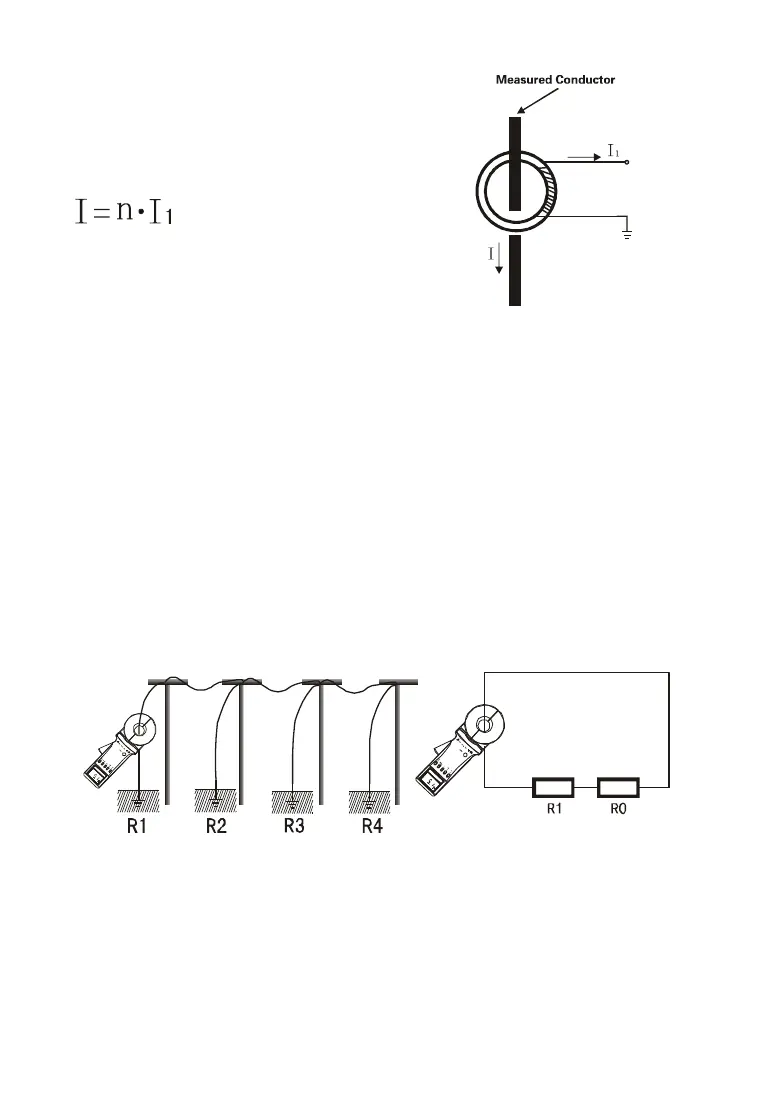
current I
1;
The Meter will measure I
1
,
and the measured current I can be
obtained by the following formula.
Where: n is the turn ratio of the
secondary side vs. primary side.
IX. Measurement Method of Earth Resistance
1. Multi-Point Grounding System
As for the multi-point grounding system (such as electricity trans-
mission tower grounding system, grounding cable communications
systems, certain buildings, etc.), They usually pass the overhead
ground wire (cable shielding layer) connected to form a grounding
system.
As the Meter is in the above measurement, its equivalent electric
circuit is shown in the figure below:
Where: R
1
is the target grounding resistance.
R
0
is the equivalent resistance of the other entire tower
grounding resistances paralleled.
Although strictly on the theoretical grounding, because of the ex-