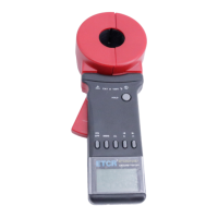
What to do if there is poor contact of battery contacts in ETCR ETCR2000E Plus Test Equipment?
- RRobert AndersonSep 13, 2025
To solve the issue of poor contact of battery contacts in your ETCR Test Equipment, replace the battery contacts.

What to do if there is poor contact of battery contacts in ETCR ETCR2000E Plus Test Equipment?
To solve the issue of poor contact of battery contacts in your ETCR Test Equipment, replace the battery contacts.
| Model | ETCR2000E Plus |
|---|---|
| Category | Test Equipment |
| Data Storage | 99 sets |
| Operating Temperature | -10°C to 55°C |
| Storage Temperature | -20°C to 60°C |
| Operating Humidity | 10% to 90% RH |
| DC Current Measurement | No |
| Ground Resistance Measurement Range | 0.01Ω-200Ω |
| Ground Voltage Measurement Range | 0.0V~600V AC |
| Resolution | 0.001Ω |
| Clamp Jaw Size | φ32mm |
| Display | LCD with backlight |
| Power Supply | 4×1.5V AA batteries |
| Battery | 4x AA batteries |
| DC Voltage Measurement | Not Applicable |
| Frequency Measurement | Not Applicable |
Essential safety guidelines for operating the clamp earth resistance tester.
Overview of the ETCR Multifunctional Clamp Earth Resistance Tester's key features and performance.
Details the different models and their corresponding jaw sizes.
Specifies the accuracy and ranges for resistance and current measurements.
Covers resolution, data memory, interfaces, power, environment, and display details.
Identifies and explains the function of each part of the clamp meter.
Explains the various symbols and indicators displayed on the LCD screen.
Details the meaning of specific symbols and error codes shown on the display.
Provides visual examples of various measurement scenarios and their display outputs.
Summarizes the functions of the meter's buttons and their respective operations.
Step-by-step guide on how to power on and initialize the clamp earth resistance tester.
Instructions on how to properly turn off the meter, including delayed shutdown.
Detailed steps for measuring earth resistance, including handling display indicators.
Guide to measuring current, including how to switch modes and interpret results.
Explains how to lock, release, and store measurement data, including memory full indications.
Instructions on how to retrieve and view previously stored measurement data.
Steps to enable/disable alarm functions and set critical alarm values.
How to view the previously set alarm critical values for resistance or current.
Procedure for deleting all stored measurement data from the device.
Instructions for connecting to a PC and using software for data monitoring and transfer.
Explains the fundamental principle behind measuring earth resistance using the clamp meter.
Details the basic principle used for measuring current with the device.
Describes how to measure resistance in multi-point grounding systems, including circuit analysis.
Explains measurement for limited point grounding, discussing mutual resistance and parallel calculations.
Details two methods (Two-Point, Three-Point) for single-point grounding measurements.
Covers usage in transmission lines, transformer neutral points, and substations.
Details usage for machine rooms and launch towers in telecommunication networks.
Explains measurements for grounding poles in lightning protection systems.
Covers grounding resistance and connection resistance testing in gas stations.
Discusses differences between ETCR and traditional methods, and why they occur.
Highlights importance of measurement point selection and understanding resistance components.
Lists all items included in the package, such as the tester, cables, and manual.
Provides a detailed list of individual components for the clamp earth resistance tester.
Illustrates the assembly process with numbered diagrams of the meter's components.
Lists common symptoms, their possible causes, and recommended remedies for the instrument.