Operation & Software Manual
322
Direct Drives & Systems
Chapter E: Appendixes ETEL Doc. - Operation & Software Manual # DSC2P 903 / Ver. F / 3/6/05
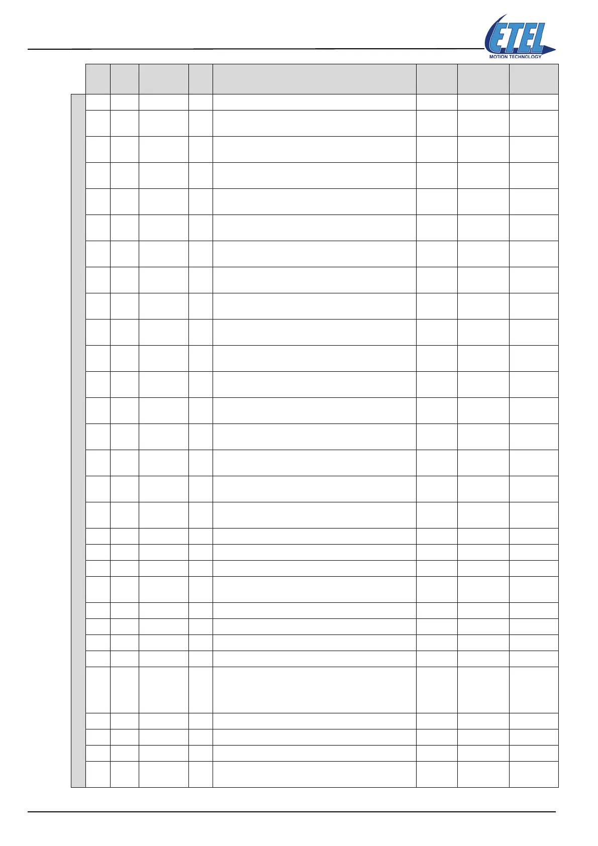
DSCDP monitorings
M63 TEB status 524288 0 4294967295
10
User word bit 0, could be modified by trigger functions or
by K177
21
User word bit 1, could be modified by trigger functions or
by K177
42
User word bit 2, could be modified by trigger functions or
by K177
83
User word bit 3, could be modified by trigger functions or
by K177
16 4
User word bit 4, could be modified by trigger functions or
by K177
32 5
User word bit 5, could be modified by trigger functions or
by K177
64 6
User word bit 6, could be modified by trigger functions or
by K177
128 7
User word bit 7, could be modified by trigger functions or
by K177
256 8
User word bit 8, could be modified by trigger functions or
by K177
512 9
User word bit 9, could be modified by trigger functions or
by K177
1024 10
User word bit 10, could be modified by trigger functions
or by K177
2048 11
User word bit 11, could be modified by trigger functions
or by K177
4096 12
User word bit 12, could be modified by trigger functions
or by K177
8192 13
User word bit 13, could be modified by trigger functions
or by K177
16384 14
User word bit 14, could be modified by trigger functions
or by K177
32768 15
User word bit 15, could be modified by trigger functions
or by K177
65536 16 The controller is in power on
524288 19 Bit present, always 1
1048576 20 The motor is executing a trajectory
2097152 21
This bit is set when the motor is in the position/time
window defined by K38 and K39
8388608 23 The controller is in warning mode
16777216 24 The controller is executing an internal sequence
67108864 26 The controller is in error mode
134217728 27 Trace busy flag is set during a register trace acquisition
1073741824 30
Position captured according to the digital input (see
K182/K178/K179). This bit is set when the conditions on
the digital input allow the capture of the position. It is
reset when 1 is written in K182
M64 Gives the error code 0 0 255
2 The current measured in phase 1 is greater than K83
3 The current measured in phase 2 is greater than K83
4
This occurs when M67 becomes greater than K85. This
is a power protection (of the motor and/or the controller)
M Alias Values
Bit #
<P1>
Comment for monitorings M
and <P1> of the DSCDP
Def. Val
<P1>
Min. Val
<P1>
Max. Val
<P1>