8
Operating Instructions
Safety Switches TZ…
EU declaration of conformity
The declaration of conformity is part of the operating
instructions, and it is included as a separate sheet
with the device.
The original EU declaration of conformity can also
be found at: www.euchner.com
Service
If servicing is required, please contact:
EUCHNER GmbH + Co. KG
Kohlhammerstraße 16
70771 Leinfelden-Echterdingen
Service telephone:
+49 711 7597-500
E-mail:
support@euchner.de
Internet:
www.euchner.com
Technical data
Parameter Value
Housing material Anodized die-cast alloy
Degree of protection
Cable entry
Plug connector
IP67
IP65
Mechanical life 1 x 10
6
operating cycles
Ambient temperature -25 … +80°C
Degree of contamination
(external, acc. to EN60947-1)
3 (industrial)
Installation orientation Any
Approach speed, max. 20 m/min
Extraction force (not locked) 30 N
Retention force 10 N
Actuating force, max. 35 N
Actuation frequency 1,200/h
Switching principle Slow-action switching contact
Contact material Silver alloy, gold flashed
Connection
TZ…
TZ…SR6
TZ…SR11
TZ…RC18
Cable entry M20 x 1.5
Plug connector SR6, 6-pin+PE
Plug connector SR11, 11-pin+PE
Plug connector RC18, 18-pin+PE
Conductor cross-section
(flexible/rigid)
0.34 … 1.5 mm²
Rated insulation voltage
TZ…M, TZ…SR6
TZ…SR11
TZ…RC18
U
i
= 250 V
U
i
= 50 V
U
i
= 110 V
Rated impulse withstand voltage
TZ…M, TZ…SR6
TZ…SR11, TZ…RC18
U
imp
= 2.5 kV
U
imp
= 1.5 kV
Conditional short-circuit
current
100 A
Switching voltage, min.,
at 10mA
12 V
Utilization category acc. to EN60947-5-1
TZ…M, TZ…SR6 AC-15 4 A 230 V /
DC-13 4 A 24 V
TZ…SR11 AC-15 4 A 50 V /
DC-13 4 A 24 V
TZ…RC18 AC-15 4 A 110 V /
DC-13 4 A 24 V
Switching current, min.,
at 24V
1 mA
Short circuit protection
(control circuit fuse)
acc. to IEC60269-1
4 A gG
Convent. thermal current I
th
4 A
Solenoid operating voltage/solenoid power consumption
TZ…024 AC/DC 24 V (+10%/-15%) 10 W
TZ…110 AC 110 V (+10%/-15%) 10 W
TZ…230 AC 230 V (+10%/-15%) 10 W
Duty cycle 100 %
Locking force F
max
F
S
= 2000 N
Locking force F
Zh
acc. to ENISO14119
(F
Zh
=
F
max
) = 1500 N
1.3
Limitations at ambient temperature above +70 ... +80 °C
Utilization category acc. to EN60947-5-1
TZ…SR6 AC-15 2 A 230 V /
DC-13 2 A 24 V
TZ…SR11 AC-15 2 A 50 V /
DC-13 2 A 24 V
Convent. thermal current I
th
2 A
Short circuit protection
according to IEC 60269-1
2 A gG
Reliability values acc. to ENISO13849-1
B
10D
at DC-13 100mA/24V
3 x 10
6
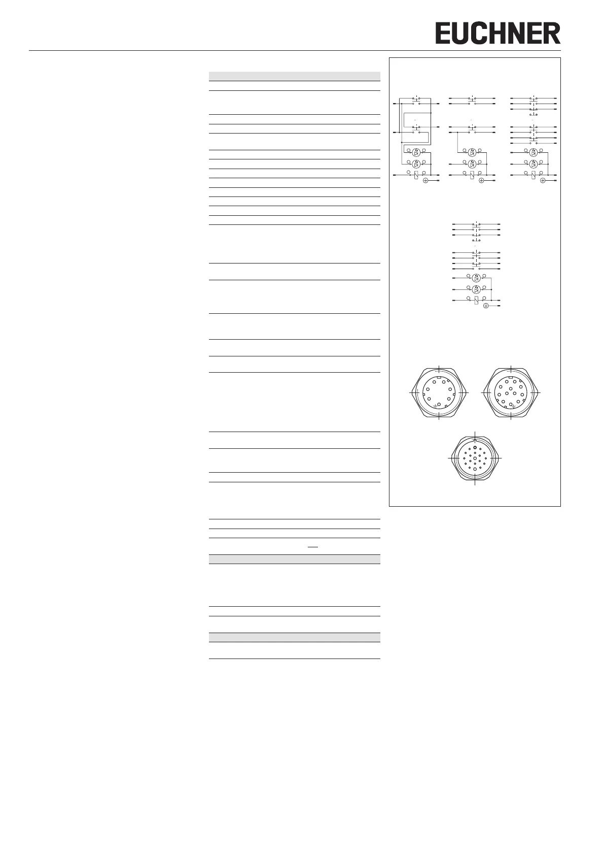
Fig. 3: Connector assignments
1
6
5
4
3
2
911
10
54
63
72
81
7
8
9
10
11
17
16
15
18
1
2
3
4
5
14
13
6
19
12
View of connection side on the safety switch
TZ..RC18
TZ..SR6 TZ..SR11
PE
3
1
1413
21 22
62
UK
SK
13
21 22
14 14
2221
13
4
3
5
6
LED
RD
2
1
16
15
41
33
42
34
14
87
13
10
2221
13 14 1817
9
3
1211
21 22
6
LEDGN
5
4
PE/12
11
12
19
UK
SK
34
42
33
41
SK
UK
3
86
9
PE
4
2
LEDG
N
2221
13 14
11
10 1
7
5
1
2
LEDRD
65
34
4
3
56
LEDRD
21
LEDGN
5
4
Illustration: guard closed, actuator locked
TZ..SR6 TZ..SR11 TZ..RC18
4
3
5
6
LED
RD
2
1
16
15
41
33
42
34
14
87
13
10
2221
13 14 1817
9
3
1211
21 22
4
LEDGN
19
6
PE/12
11
12
5
UK
SK
34
42
33
41
TZ..RC18...C1826