20 mm
8
3.4.5. GATE BRACKET S4 (for Stilo S only)
To determine the position of bracket S4:
Put the gate in closing position
Release the operator (see paragraph 4)
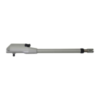
Move forward the front pivot of the operator until it reaches the position of limit switch in opening. Leave 20mm of space between the pivot
and the operator end (fig. O)
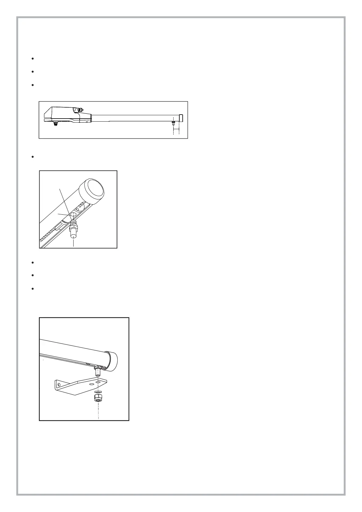
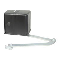
Fasten bracket S4 to the front pivot of the operator as indicated in pic. Q keeping in mind that the threaded hole of the rotating pivot must be
turned down and that the dragging pivot milling must be placed longitudinally to the hole (pic. P).
Put the operator on the gate’s wing keeping it levelled and mark the position of bracket S4 on the gate.
Weld or bolt bracket S4 to the gate.
Control that the drag pin has been positioned with the two sides of the milling in parallel position to the button hole of the alum. tube as
indicated in the pic. Q.
Pic. O
Pic. P
Pic. Q
Milling
Button hole